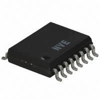
IL3185E NVE, IL3185E Datasheet - Page 7

IL3185E
Manufacturer Part Number
IL3185E
Description
TXRX ISO BUS 5MBPS RS485 16SOIC
Manufacturer
NVE
Series
IsoLoop®r
Datasheet
1.IL3185-3E.pdf
(15 pages)
Specifications of IL3185E
Inputs - Side 1/side 2
RS-485
Number Of Channels
1
Isolation Rating
2500Vrms
Voltage - Supply
4.25V, 5V
Data Rate
5Mbps
Propagation Delay
55ns
Output Type
Logic
Package / Case
16-SOIC (0.300", 7.5mm Width)
Operating Temperature
-40°C ~ 85°C
Device Type
Differential Transceiver
Ic Interface Type
RS422, RS485
No. Of Drivers
1
Supply Voltage Range
3V To 5.5V
Driver Case Style
SOIC
No. Of Pins
16
Lead Free Status / RoHS Status
Lead free / RoHS Compliant
Other names
390-1095-5
Available stocks
Company
Part Number
Manufacturer
Quantity
Price
Part Number:
IL3185E
Manufacturer:
NVE
Quantity:
20 000
Power Supply Decoupling
Both V
proper operation. Additionally, V
Operation
Coil Current
Figure 1. IL3000 Series Input Transfer Function
Typical Resistor Values
Boost Capacitor
The correct boost capacitor gives a great deal of design headroom and can usually eliminate design concerns related to temperature
and power supply fluctuations.
Logic State
V
3.3 V
5 V
Figure 2. C
Rise/Fall Time (ns)
Rise/Fall Time (ns)
NVE Corporation
COIL
High
Low
mA
3.5
1.5
DD1
Signal
Signal
5
and V
1000
boost
1000
500
0.125W, 5% Resistor
510 Ω
820 Ω
20
50
3
3
DD2
Selector
11409 Valley View Road, Eden Prairie, MN 55344-3617
must be bypassed with 47 nF ceramic capacitors. These should be placed as close as possible to V
16
16
C
C
Boost
Boost
( pF )
( pF )
100
2500
DD2
should be bypassed with a 10 µF tantalum capacitor.
210
5000
5000
The table shows typical values for the external resistor in 5 V and 3 V logic systems.
As always, these values as approximate and should be adjusted for temperature or
other application specifics If the expected temperature range is large, 1% tolerance
resistors may provide additional design margin.
t
t
The boost capacitor in parallel with the current-limiting resistor boosts
the instantaneous coil current at the signal transition. The boost current
pushes the GMR bridge output through the comparator threshold voltage
in a bipolar fashion providing important magnetic centering and very
reliable switching. Select the value of the boost capacitor based on the
rise and fall times of the signal driving the inputs.
Use the chart as a guide to boost capacitor selection. The capacitor value
is generally not critical, and can often vary ±50% with little noticeable
difference in device performance provided the center value is correct. If
in doubt, choose a value higher than indicated, up to a maximum of
470 nF. Note however that power dissipation in the input coil increases in
proportion to the capacitor value.
The IL3122 and IL3185 are current-mode devices. Changes in input coil
current switch internal spintronic GMR sensors, which then change the
logic state of the outputs. The GMR bridge is designed so the output of
the isolator is logic high when no field signal is present.
A single resistor is required to limit the input coil current to the
recommended 5 mA. The absolute maximum current through any coil is
25 mA DC. Although logic threshold currents are typically less than the
worst-case 5 mA, NVE recommends designing for 5 mA logic threshold
current in all applications.
Figure 1 shows the input response of the IL3122 and IL3185.
logic high is the zero input current state.
with approximately 3.5 mA of coil current, and back to the high state
when the input current falls below approximately 1.5 mA. This allows
glitch-free interface with low slew-rate signals.
Phone: (952) 829-9217
7
Fax: (952) 829-9189
The output switches to the low state
IL3185/IL3122
www.IsoLoop.com
©NVE Corporation
DD
Output
pins for


