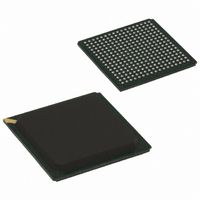
KS8695PI Micrel Inc, KS8695PI Datasheet - Page 26

KS8695PI
Manufacturer Part Number
KS8695PI
Description
IC ARM9 W/MMU 5PORT 289-PBGA
Manufacturer
Micrel Inc
Specifications of KS8695PI
Applications
*
Mounting Type
Surface Mount
Package / Case
289-PBGA
Operating Supply Voltage (typ)
1.8/3.3V
Operating Supply Voltage (min)
1.7/3V
Operating Supply Voltage (max)
1.9/3.6V
Operating Temp Range
-40C to 85C
Operating Temperature Classification
Industrial
Mounting
Surface Mount
Pin Count
289
Lead Free Status / RoHS Status
Contains lead / RoHS non-compliant
For Use With
KS8695P-MDP-EVAL - EVAL KIT EXPERIMENTAL KS8695PMPDKS8695-EVAL - EVAL KIT EXPERIMENTAL KS8695576-1003 - BOARD EVAL MULTIMEDIA KS8695P
Lead Free Status / RoHS Status
Not Compliant, Contains lead / RoHS non-compliant
Available stocks
Company
Part Number
Manufacturer
Quantity
Price
LAN Ethernet Physical Interface Pins
PHY LED Drivers
Note:
1. I = Input.
Micrel, Inc.
May 2006
C17
D17
C16
D16
E15
E14
B17
E17
B16
E16
Pin
Pin
H1
K1
H2
K2
H3
K3
H4
K4
L1
L2
L3
L4
F1
F3
J1
J2
J3
J4
O = Output.
O/I = Output in normal mode; input pin during reset.
LANFXSD1
LANRXM1
LANRXM2
LANRXM3
LANRXM4
LANTXM1
LANTXM2
LANTXM3
LANTXM4
LANTXP1
LANTXP2
LANTXP3
LANTXP4
LANRXP1
LANRXP2
LANRXP3
LANRXP4
B0SIZE0
B0SIZE1
WLED0/
WLED1/
L1LED0
L2LED0
L3LED0
L4LED0
L1LED1
L2LED1
L3LED1
L4LED1
Name
Name
ISET
I/O Type
I/O Type
O/I
O/I
O
O
O
O
I
I
I
I
(1)
(1)
Description
LAN Port[4:1] PHY transmit signal + (differential).
LAN Port[4:1] PHY transmit signal – (differential).
LAN Port[4:1] PHY receive signal + (differential).
LAN Port[4:1] PHY receive signal – (differential).
Set PHY transmit output current. Connect to ground through a 3.01kΩ 1% resistor.
LAN fiber signal detect. Signal detect input when the LAN1 port is operated in
100BASE-FX 100Mb fiber mode. See Application Note 107.
Description
Normal Mode: WAN LED indicator 0. Programmable via WAN misc. Control register
bits [2:0].
‘000’ = Speed; ‘001’ = Link; ‘010’ = Full/half duplex; ‘011’ = Collision;
‘100’ = TX/RX activity; ‘101’ = Full-duplex collision; ‘110’ = Link/Activity.
During reset: Bank 0 Data Access Size. Bank 0 is used for the boot program.
B0SIZE[1:0] are used to specify the size of the bank 0 data bus width as follows:
‘01’ = one byte, ‘10’ = half-word, ‘11’ = one word, and ‘00’ = reserved.
Normal Mode: WAN LED indicator 1. Programmable via WAN Misc. Control register
bits [6:4].
‘000’ = Speed; ‘001’= Link; ‘010’ = Full/half duplex; ‘011’ = Collision;
‘100’ = TX/RX activity; ‘101’ = Full-duplex collision; ‘110’ = Link/Activity.
During reset: Bank 0 data access size. Bank 0 is used for the boot program.
B0SIZE[1:0] are used to specify the size of the bank 0 data bus width as follows:
‘01’ = one byte, ‘10’ = half-word, ‘11’ = one word, and ‘00’ = reserved.
LAN Port[4:1] LED indicator 0. Programmable via switch control 0 register bits
[27:25].
‘000’ = Speed; ‘001’ = Link; ‘010’ = Full/half duplex; ‘011’ = Collision;
'100’ = TX/RX activity; ‘101’ = Full-duplex collision; ‘110’ = Link/Activity.
LAN Port[4:1] LED indicator 1. Programmable via switch control 0 register bits
[24:22].
‘000’ = Speed; ‘001’ = Link; ‘010’ = Full/half duplex; ‘011’ = Collision;
‘100’ = TX/RX activity; ‘101’ = Full-duplex collision; ‘110’ = Link/Activity.
26
M9999-051806
KS8695P


