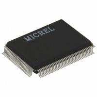
KS8893MQL Micrel Inc, KS8893MQL Datasheet - Page 40

KS8893MQL
Manufacturer Part Number
KS8893MQL
Description
IC MANAGED SWITCH 10/100 128PQFP
Manufacturer
Micrel Inc
Specifications of KS8893MQL
Applications
*
Mounting Type
Surface Mount
Package / Case
128-MQFP, 128-PQFP
Number Of Primary Switch Ports
3
Internal Memory Buffer Size
32
Operating Supply Voltage (typ)
3.3V
Fiber Support
Yes
Integrated Led Drivers
Yes
Power Supply Type
Analog/Digital
Package Type
PQFP
Data Rate (typ)
10/100Mbps
Vlan Support
Yes
Operating Temperature (max)
70C
Operating Temperature (min)
0C
Pin Count
128
Mounting
Surface Mount
Jtag Support
No
Operating Supply Voltage (max)
3.5V
Operating Supply Voltage (min)
3.1V
Operating Temperature Classification
Commercial
Data Rate
100Mbps
Lead Free Status / RoHS Status
Lead free / RoHS Compliant
Other names
576-1457
Available stocks
Company
Part Number
Manufacturer
Quantity
Price
The MII operates in either PHY mode or MAC mode. The data interface is a nibble wide and runs at ¼ the
network bit rate (not encoded). Additional signals on the transmit side indicate when data is valid or when an error
occurs during transmission. Similarly, the receive side has signals that convey when the data is valid and without
physical layer errors. For half duplex operation, the SCOL signal indicates if a collision has occurred during
transmission.
The KSZ8893MBL does not provide the MRXER signal for PHY mode operation and the MTXER signal for MAC
mode operation. Normally, MRXER indicates a receive error coming from the physical layer device and MTXER
indicates a transmit error from the MAC device. Since the switch filters error frames, these MII error signals are
not used by the KSZ8893MBL. So, for PHY mode operation, if the device interfacing with the KSZ8893MBL has
an MRXER input pin, it needs to be tied low. And, for MAC mode operation, if the device interfacing with the
KSZ8893MQL/MBL has an MTXER input pin, it also needs to be tied low.
RMII Interface Operation
The Reduced Media Independent Interface (RMII) specifies a low pin count Media Independent Interface (MII).
RMII provides a common interface between physical layer and MAC layer devices, and has the following key
characteristics:
1. Supports 10Mbps and 100Mbps data rates.
2. Uses a single 50 MHz clock reference (provided externally).
3. Provides independent 2-bit wide (di-bit) transmit and receive data paths.
4. Contains two distinct groups of signals: one for transmission and the other for reception
The RMII provided by the KSZ8893MQL/MBL is connected to the device’s third MAC. It complies with the RMII
Specification. The following table describes the signals used by the RMII bus. Refer to RMII Specification for full
detail on the signal description.
December 2007
RMII
Signal Name
REF_CLK
CRS_DV
RXD1
RXD0
TX_EN
TXD1
TXD0
RX_ER
---
Direction
(with respect
to the PHY)
Input
Output
Output
Output
Input
Input
Input
Output
---
Direction
(with respect
to the MAC)
Input or
Output
Input
Input
Input
Output
Output
Output
Input
(not required)
---
Table 4: RMII Signal Description
RMII
Signal Description
Synchronous 50 MHz clock
reference for receive, transmit
and control interface
Carrier sense/
Receive data valid
Receive data bit 1
Receive data bit 0
Transmit enable
Transmit data bit 1
Transmit data bit 0
Receive error
---
40
KSZ8893MQL/MBL RMII
Signal (direction)
REFCLK (input)
SMRXDV (output)
SMRXD[1] (output)
SMRXD[0] (output)
SMTXEN (input)
SMTXD[1] (input)
SMTXD[0] (input)
(not used)
SMTXER* (input)
* Connects to RX_ER signal
of RMII PHY device
M9999-121007-1.5


