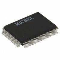
KS8995MI Micrel Inc, KS8995MI Datasheet - Page 16

KS8995MI
Manufacturer Part Number
KS8995MI
Description
IC SWITCH 10/100 5PORT 128PQFP
Manufacturer
Micrel Inc
Specifications of KS8995MI
Applications
*
Mounting Type
Surface Mount
Package / Case
128-MQFP, 128-PQFP
Number Of Primary Switch Ports
5
Internal Memory Buffer Size
64
Operating Supply Voltage (typ)
1.8/2.5/3.3V
Fiber Support
Yes
Integrated Led Drivers
Yes
Phy/transceiver Interface
MII/SNI
Power Supply Type
Analog/Digital
Package Type
PQFP
Data Rate (typ)
10/100Mbps
Vlan Support
Yes
Operating Temperature (max)
85C
Operating Temperature (min)
-40C
Pin Count
128
Mounting
Surface Mount
Jtag Support
No
Operating Supply Voltage (max)
1.9/2.6/3.6V
Operating Supply Voltage (min)
1.7/2.4/3V
Operating Temperature Classification
Industrial
Data Rate
100Mbps
Lead Free Status / RoHS Status
Contains lead / RoHS non-compliant
For Use With
576-1017 - BOARD EVAL EXPERIMENT KS8995M
Lead Free Status / RoHS Status
Not Compliant, Contains lead / RoHS non-compliant
Other names
576-1020
Available stocks
Company
Part Number
Manufacturer
Quantity
Price
KS8995M
Note:
1. P = Power supply
M9999-062309
Pin Number
I = Input
O = Output
I/O = Bi-directional
Gnd = Ground
Ipu = Input w/ internal pull-up
Ipd = Input w/ internal pull-down
Ipd/O = Input w/ internal pull-down during reset, output pin otherwise
Ipu/O = Input w/ internal pull-up during reset, output pin otherwise
PU = Strap pin pull-up
PD = Strap pin pull-down
Otri = Output tristated
NC = No Connect
107
108
97
96
95
94
93
92
91
90
45
46
68
67
60
65
64
63
62
1
Pin Name
PMRXD0
PMRXD1
PMRXD2
PMRXD3
PMRXC
LED3-1
LED3-2
LED4-0
LED4-1
LED4-2
LED5-0
LED5-1
LED5-2
TEST1
MUX1
MUX2
PCOL
PCRS
MDIO
MDC
Type
Ipu/O
Ipu/O
Ipu/O
Ipu/O
Ipu/O
Ipu/O
Ipu/O
Ipu/O
Ipd/O
Ipd/O
Ipd/O
Ipd/O
Ipd/O
Ipd/O
Ipu
NC
NC
NC
I/O
O
(1)
Port
All
All
3
3
4
4
4
5
5
5
5
5
5
5
5
5
5
Pin Function
LED indicator 1
LED indicator 2
LED indicator 0
LED indicator 1
LED indicator 2
LED indicator 0
LED indicator 1. Strap option: PU (default): enable PHY MII I/F.
PD: tristate all PHY MII output. See “pin# 86 SCONF1.”
LED indicator 2. Strap option: Aging setup. See “Aging” section.
(default) = Aging Enable; PD = Aging disable
Switch or PHY[5] MII management data clock.
Switch or PHY[5] MII management data I/O.
NC for normal operation. Factory test pin.
MUX1 and MUX2 should be left unconnected for normal operation.
They are factory test pins.
Mode
Normal Operation
Remote Analog Loopback Mode for Testing only
Reserved
Power Save Mode for Testing only
PHY[5] MII collision detect. Strap option for port 4 only. See “Register 18.”
PD (default) = No force flow control. PU = Force flow control.
PHY[5] MII carrier sense. Strap option for port 4 only. See “Register 28.”
PD (default) = Force half-duplex if auto-negotiation is disabled or fails.
PU = Force full-duplex if auto-negotiation is disabled or fails.
PHY[5] MII receive clock. PHY mode MII.
PHY[5] MII receive bit 0. Strap option: PD (default) = disable
aggressive back-off algorithm in half-duplex mode; PU = enable for
performance enhancement.
PHY[5] MII receive bit 1. Strap option: PD (default) = drop excessive
collision packets; PU = does not drop excessive collision packets.
PHY[5] MII receive bit 2. Strap option: PD (default) = disable back
pressure; PU = enable back pressure.
PHY[5] MII receive bit 3. Strap option: PD (default) = enable flow
control; PU = disable flow control.
16
MUX1
NC
0
1
1
Micrel, Inc.
June 2009
MUX2
NC
1
0
1


