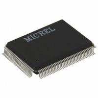
KS8995M Micrel Inc, KS8995M Datasheet - Page 34

KS8995M
Manufacturer Part Number
KS8995M
Description
IC SWITCH 10/100 5PORT 128PQFP
Manufacturer
Micrel Inc
Specifications of KS8995M
Applications
*
Mounting Type
Surface Mount
Package / Case
128-MQFP, 128-PQFP
Number Of Primary Switch Ports
5
Internal Memory Buffer Size
64
Operating Supply Voltage (typ)
1.8/2.5/3.3V
Fiber Support
Yes
Integrated Led Drivers
Yes
Phy/transceiver Interface
MII/SNI
Power Supply Type
Analog/Digital
Package Type
PQFP
Data Rate (typ)
10/100Mbps
Vlan Support
Yes
Operating Temperature (max)
70C
Operating Temperature (min)
0C
Pin Count
128
Mounting
Surface Mount
Jtag Support
No
Operating Supply Voltage (max)
1.9/2.6/3.6V
Operating Supply Voltage (min)
1.7/2.4/3V
Operating Temperature Classification
Commercial
Data Rate
100Mbps
Lead Free Status / RoHS Status
Lead free / RoHS Compliant
For Use With
576-1017 - BOARD EVAL EXPERIMENT KS8995M
Lead Free Status / RoHS Status
Not Compliant, Lead free / RoHS Compliant
Available stocks
Company
Part Number
Manufacturer
Quantity
Price
Company:
Part Number:
KS8995M
Manufacturer:
MICREL
Quantity:
1 820
Company:
Part Number:
KS8995MAI
Manufacturer:
MAXIM
Quantity:
4 430
KS8995M
M9999-062309
Pin #
113
114
128
86
87
90
91
Pin Name
SCONF1
SCONF0
LED5-2
LED5-1
TEST2
PS1
PS0
PU/PD
Ipu/O
Ipu/O
NC
Ipd
Ipd
Ipd
Ipd
Description
Dual MII configuration pin.
Pin# (91, 86, 87):
000
001
010
011
100
101
110
111
Dual MII configuration pin.
LED indicator 2. Strap option: Aging setup. See “Aging” section.
PU (default) = Aging Enable; PD = Aging disable.
LED indicator 1. Strap option: PU (default): enable PHY MII I/F. PD: tristate all PHY
MII output. See “pin# 86 SCONF1. ”
Serial bus configuration pin
If EEPROM is not present, the KS8995M will start itself with chip
default (00)...
Pin Configuration
PS[1:0]=00
PS[1:0]=01
PS[1:0]=10
PS[1:0]=11
Serial bus configuration pin. See “pin# 113.”
NC for normal operation. Factory test pin.
34
Switch MII
Disable, Otri
PHY Mode MII
MAC Mode MII
PHY Mode SNI
Disable
PHY Mode MII
MAC Mode MII
PHY Mode SNI
Serial Bus Configuration
I2C Master Mode for EEPROM
Reserved
SPI Slave Mode for CPU Interface
Factory Test Mode (BIST)
PHY [5] MII
Disable, Otri
Disable, Otri
Disable, Otri
Disable, Otri
Disable
PHY Mode MII
PHY Mode MII
PHY Mode MII
Micrel, Inc.
June 2009


