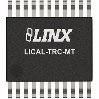
LICAL-TRC-MT Linx Technologies Inc, LICAL-TRC-MT Datasheet - Page 7

LICAL-TRC-MT
Manufacturer Part Number
LICAL-TRC-MT
Description
IC TRANSCODER MT BI-DIR 20-SSOP
Manufacturer
Linx Technologies Inc
Series
MTr
Type
Transcoderr
Specifications of LICAL-TRC-MT
Package / Case
20-SSOP
Applications
RF, IR
Mounting Type
Surface Mount
Supply Voltage (max)
5.5 V
Supply Voltage (min)
2 V
Maximum Operating Temperature
+ 85 C
Minimum Operating Temperature
- 40 C
Mounting Style
SMD/SMT
Lead Free Status / RoHS Status
Lead free / RoHS Compliant
Lead Free Status / RoHS Status
Lead free / RoHS Compliant, Lead free / RoHS Compliant
Other names
LICAL-TRC-MTTR
Available stocks
Company
Part Number
Manufacturer
Quantity
Price
SERIAL INTERFACE COMMAND SET DEFINITIONS
Page 12
Local Settings
Next User ID
Specific User
Target Address
Custom Data Value
Latch Mask
Status Value
Confirmation EN
Targeting EN
Custom Data EN
There are nine functions using the Serial Interface Engine (SIE). Each function
has the ability to read the current setting from the MT or write new information to
the specified configuration setting.
Command
Reads and writes the device’s local 24-bit address and status line
configuration. This allows the option to program all devices with
the same address and status line configuration, or increment the
address to utilize the full range of addresses.
Reads and writes the next available ID location, which will be
given to the next user manually learned into the system.
Reads and writes the 24-bit address and status line configuration
for a specific user learned into the system. If a device in the
system is lost or stolen, that specific device can be removed from
the system and replaced with a new one without having to erase
the memory and re-learn all of the other devices in the system.
To remove an existing user, write 0xFF into the address and
status line values. 0xFF should not be used as a learned user.
Reads and writes the local device’s 24-bit target address. This
allows a user to communicate directly with a specified target
device and not with any other devices even though they may have
been authorized for communication.
Reads and writes a single byte that is sent when Custom Data is
enabled. If enabled, the byte will be sent with each packet, and
then output on the SER_IO line of the receiving device along with
the TX ID value and the status line value.
Reads and writes the Latch Mask for the status line outputs. This
allows each status line to be individually set as momentary or
latched.
Reads the current state of the transcoder’s status line outputs.
Writes the value of the status line inputs to be sent (subject to I/O
mask) and the number of packets to send.
Reads and writes the device’s confirmation enable setting. When
enabled, the receiving transcoder will immediately transmit a
confirmation packet back to the originating transcoder. The
originating transcoder will validate the confirmation and then
activate its CONFIRM line. If the confirmation is not necessary or
the user wants to free the air of additional transmissions,
confirmation can be disabled and the receiving device will not
transmit a confirmation packet.
Reads and writes the device’s target enable setting. This enables
or disables the option for the transcoder to send a targeted data
packet.
Reads and writes the transcoder’s custom data setting. This
enables or disables the option for the transcoder to send a custom
data byte with each transmission.
Description
SERIAL INTERFACE CONNECTIONS
Figure 7: MT Series Transcoder Serial Interface to a PC
USB Type B
Connector
The serial interface on the MT Series can be connected to any device capable
of serial communication, including microcontrollers, RS-232 drivers, and
computers. The figure below gives an example of connecting the MT to the Linx
QS Series USB module for connection to a computer.
The USB module follows the RS-232 convention of using separate lines for data
input and data output while the transcoder has a single line for all data. This
requires a switch to alternatively connect the transcoder’s SER_IO line to the
data lines on the module.
The RTS line is used to throw the switch as well as to activate the CRT/LRN line
placing the transcoder into Serial Mode. This gives the PC the ability to control
when communication is initiated.
The MODE_IND line will go high when the transcoder is prepared to send data,
so the CTS line on the USB module is used to monitor the MODE_IND line. This
allows the computer to know when to throw the switch and look for data from the
transcoder.
One point of note is that voltage translation may be necessary if the 5V USB
module is used to communicate with a transcoder operating at 3V. There are
many components and methods for implementing level shifting, so it is up to the
designer to determine the best solution for the product.
DAT+
DAT -
GND
5V
4
3
2
1
GND
1
2
3
4
5
6
7
8
USBDP
USBDM
GND
VCC
SUSP_IND
RX_IND
TX_IND
485_TX
SDM-USB-QS
DATA_OUT
DATA_IN
DCD
DSR
RTS
CTS
DTR
RI
16
15
14
13
12
10
11
9
VCC
10
1
2
3
4
5
6
7
8
9
1
2
3
4
GND
VCC
D6
D7
CRT/LRN
ENC_SEL
SER_IO
CONFIRM
TR_PDN
TR_SEL
TR_DATA
MAX4544
LICAL-TRC-MT
NC
NC
V+
8
6
5
7
VCC
SEL_BAUD
MODE_IND
LATCH
GND
D5
D4
D3
D2
D1
D0
20
19
18
17
16
15
14
13
12
11
Page 13


