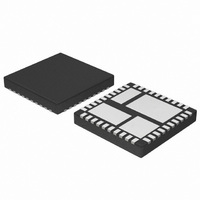
NCP3101MNTXG ON Semiconductor, NCP3101MNTXG Datasheet - Page 10

NCP3101MNTXG
Manufacturer Part Number
NCP3101MNTXG
Description
IC CONV VOLT SYNC BUCK 6A 40-QFN
Manufacturer
ON Semiconductor
Type
Step-Down (Buck)r
Datasheet
1.NCP3101BMNTXG.pdf
(26 pages)
Specifications of NCP3101MNTXG
Internal Switch(s)
Yes
Synchronous Rectifier
Yes
Number Of Outputs
1
Voltage - Output
Adj to 0.8V
Current - Output
6A
Frequency - Switching
275kHz
Voltage - Input
4.5 ~ 13.2 V
Operating Temperature
-40°C ~ 85°C
Mounting Type
Surface Mount
Package / Case
40-TQFN Exposed Pad
Power - Output
3W
Lead Free Status / RoHS Status
Lead free / RoHS Compliant
Normal Shutdown Behavior
because the input supply reaches UVLO threshold. In this
case, switching stops, the internal soft start, SS, is
discharged, and all gate pins go low. The switch node enters
a high impedance state and the output capacitors discharge
through the load with no ringing on the output voltage.
External Soft−Start
which reduces inrush current and overshoot of the output
voltage. Soft start is achieved by using the internal current
source of 10 mA (typ), which charges the external integrator
capacitor of the transconductance amplifier. Figures 22
and 23 are typical soft start sequences. The sequence begins
once V
as the Comp Pin rises through 400 mV, the PWM logic and
gate drives are enabled. When the feedback voltage crosses
800 mV, the EOTA will be given control to switch to its
higher regulation mode with the ability to source and sink
130 mA. In the event of an over current during the soft start,
the overcurrent logic will override the soft start sequence
and will shut down the PWM logic and both the high side and
low side gates of the switching MOSFETS.
Isource/
sink
Enable
Vcomp
Normal shutdown occurs when the IC stops switching
The NCP3101C features an external soft start function,
Vfb
CC
10uA
Figure 22. Soft−Start Implementation
surpasses its UVLO threshold. During Soft Start
−10uA
Start up
0.4V
0.83V
SS
Normal
120uA
0.8V
0.4V
http://onsemi.com
10uA
10
UVLO
unexpected behavior does not occur when V
support the internal rails and power the converter. For the
NCP3101C, the UVLO is set to ensure that the IC will start
up when VCC reaches 4.0 V and shutdown when V
below 3.6 V. The UVLO feature permits smooth operation
from a varying 5.0 V input source.
Current Limit Protection
FET will conduct large currents. The low−side R
is implemented to protect from over current by comparing
the voltage at the phase node to AGND just prior to the low
side MOSFET turnoff to an internally generated fixed
voltage. If the differential phase node voltage is lower than
OC trip voltage, an overcurrent condition occurs and a
counter is initiated. If seven consecutive over current trips
are counted, the PWM logic and both HS−FET and LS−FET
are turned off. The converter will be latched off until input
power drops below the UVLO threshold. The operation of
key nodes are displayed in Figure 24 for both normal
operation and during over current conditions.
VCC
COMP
VFB
BG
TG
BG Comparator
DAC Voltage
BG Comparator
Output
Vout
Under Voltage Lockout (UVLO) is provided to ensure that
In case of a short circuit or overload, the low−side (LS)
UVLO
4.3 V
Delay
POR
Figure 23. Soft−Start Sequence
50mV
Current
Trip Set
COMP
500mV
Delay
0.9 V
Normal Operation
CC
is too low to
DS(on)
3.4 V
CC
UVLO
drops
sense


