MIC4576-5.0BU Micrel Inc, MIC4576-5.0BU Datasheet - Page 6
MIC4576-5.0BU
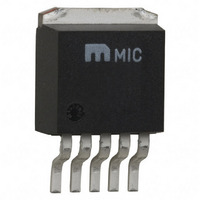
Manufacturer Part Number
MIC4576-5.0BU
Description
IC REG 200KHZ 3.0A 5.0V TO-263-5
Manufacturer
Micrel Inc
Type
Step-Down (Buck)r
Datasheet
1.MIC4576WU_TR.pdf
(8 pages)
Specifications of MIC4576-5.0BU
Internal Switch(s)
Yes
Synchronous Rectifier
No
Number Of Outputs
1
Voltage - Output
5V
Current - Output
3A
Frequency - Switching
200kHz
Voltage - Input
4 ~ 36 V
Operating Temperature
-40°C ~ 85°C
Mounting Type
Surface Mount
Package / Case
D²Pak, TO-263 (5 leads + tab)
Lead Free Status / RoHS Status
Contains lead / RoHS non-compliant
Power - Output
-
Available stocks
Company
Part Number
Manufacturer
Quantity
Price
Company:

Part Number:
MIC4576-5.0BU
Manufacturer:
MIC
Quantity:
130
Part Number:
MIC4576-5.0BU
Manufacturer:
MIC
Quantity:
20 000


Functional Description
The MIC4576 is a variable duty cycle switch-mode regulator
with an internal power switch. Refer to the block diagrams.
Supply Voltage
The MIC4576 operates from a +4V to +36V unregulated
input. Highest efficiency operation is from a supply voltage
around +15V.
Enable/Shutdown
The shutdown (
input if unused. A logic-low enables the regulator. A logic-
high shuts down the internal regulator which reduces the
current to typically 50µA.
Feedback
Fixed versions of the regulator have an internal resistive
divider from the feedback (
the output line.
Adjustable versions require an external resistive voltage
divider from the output voltage to ground, connected from
the 1.23V tap to
Duty Cycle Control
A fixed-gain error amplifier compares the feedback signal
with a 1.23V bandgap voltage reference. The resulting error
amplifier output voltage is compared to a 200kHz sawtooth
waveform to produce a voltage controlled variable duty cycle
output.
Applications Information
The applications circuits that follow have been constructed
and tested. Refer to Application Note 15 for additional in-
formation, including efficiency graphs and manufacturer’s
addresses and telephone numbers for most circuits.
Note 2:
MIC4576
Figure 1. 6V–24V to 3.3V/3A Buck Converter
6V to 24V
470µF
Surface-mount component.
35V
C1
C1 Nichicon
C2 Nichicon
D1 Motorola
L1 Coiltronics PL52C-33-1000, DCR = 0.036Ω
L1 Bi
SHDN
5
1
FB
SHDN
V
MIC4576-3.3BT
IN
.
) input is TTL compatible. Ground the
UPL1V471MPH, ESR = 0.046Ω
UPL1C221MPH, ESR = 0.047Ω
1N5822
HM77-30004, DCR = 0.045Ω, Note 2
Through Hole
GND
3
FB
SW
FB
) pin. Connect
2
4
D1
1N5822
33µH
L1
3.3V/3A
FB
C2
1000µF
16V
directly to
6
A higher feedback voltage increases the error amplifier output
voltage. A higher error amplifier voltage (comparator inverting
input) causes the comparator to detect only the peaks of the
sawtooth, reducing the duty cycle of the comparator output.
A lower feedback voltage increases the duty cycle.
Output Switching
When the internal switch is on, an increasing current flows
from the supply V
output capacitor C
inductor as the current increases with time.
When the internal switch is turned off, the collapse of the
magnetic field in L1 forces current to flow through fast recovery
diode D1, charging C
Output Capacitor
External output capacitor C
reduces ripple.
Return Paths
During the on portion of the cycle, the output capacitor and
load currents return to the supply ground. During the off
portion of the cycle, current is being supplied to the output
capacitor and load by storage inductor L1, which means that
D1 is part of the high-current return path.
For a mathematical approach to component selection and
circuit design, refer to Application Note 14.
Figure 2. 6V–36V to 3.3V/3A Buck Converter
6V to 36V
470µF
63V
C1
C1 Nichicon
C2 Nichicon
D1 Motorola
L1 Coiltronics PL52C-33-1000 DCR = 0.036
L1 Bi
5
1
IN,
SHDN
V
OUT
MIC4576-3.3BT
IN
through external storage inductor L1, to
OUT
UPL1J471MRH, ESR = 0.039Ω
UPL1C102MPH, ESR = 0.047Ω
MBR360
HM77-30004, DCR = 0.045Ω, Note 2
Through Hole
GND
and the load. Energy is stored in the
3
.
OUT
SW
FB
2
4
provides stabilization and
D1
MBR360
33µH
L1
3.3V/3A
C2
1000µF
16V
March 2006
Related parts for MIC4576-5.0BU
Image
Part Number
Description
Manufacturer
Datasheet
Request
R

Part Number:
Description:
IC REG 200KHZ 3.0A 5.0V TO-263-5
Manufacturer:
Micrel Inc
Datasheet:
Part Number:
Description:
IC REG BUCK 3.0A 3.3V TO-263-5
Manufacturer:
Micrel Inc
Datasheet:

Part Number:
Description:
IC REG 200KHZ 3.0A 3.3V TO-220-5
Manufacturer:
Micrel Inc
Datasheet:
Part Number:
Description:
IC REG 200KHZ 3.0A 3.3V TO-263-5
Manufacturer:
Micrel Inc
Datasheet:
Part Number:
Description:
IC REG 200KHZ 3.0A 5.0V TO-220-5
Manufacturer:
Micrel Inc
Datasheet:
Part Number:
Description:
IC REG 200KHZ 3.0A 5.0V TO-263-5
Manufacturer:
Micrel Inc
Datasheet:
Part Number:
Description:
IC REG 200KHZ 3.0A 3.3V TO-263-5
Manufacturer:
Micrel Inc
Datasheet:
Part Number:
Description:
IC REG 200KHZ 3.0A 5.0V TO-263-5
Manufacturer:
Micrel Inc
Datasheet:
Part Number:
Description:
IC REG 200KHZ 3.0A 3.3V TO263-5
Manufacturer:
Micrel Inc
Datasheet:
Part Number:
Description:
IC REG 200KHZ 3.0A 3.3V TO-220-5
Manufacturer:
Micrel Inc
Datasheet:
Part Number:
Description:
IC REG 200KHZ 3.0A 5.0V TO-220-5
Manufacturer:
Micrel Inc
Datasheet:

Part Number:
Description:
Manufacturer:
Micrel Inc
Datasheet:
Part Number:
Description:
Manufacturer:
Micrel Inc
Datasheet:
Part Number:
Description:
Manufacturer:
Micrel Inc
Datasheet:
Part Number:
Description:
Manufacturer:
Micrel Inc
Datasheet: