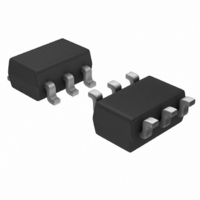
IRU3065CLTR International Rectifier, IRU3065CLTR Datasheet - Page 12

IRU3065CLTR
Manufacturer Part Number
IRU3065CLTR
Description
IC POS-NEG DC-DC CNTRLR SOT23-6
Manufacturer
International Rectifier
Type
Invertingr
Specifications of IRU3065CLTR
Internal Switch(s)
No
Synchronous Rectifier
No
Number Of Outputs
1
Voltage - Output
Adjustable
Current - Output
1A
Frequency - Switching
Adj to 1.5MHz
Voltage - Input
5V
Operating Temperature
0°C ~ 70°C
Mounting Type
Surface Mount
Package / Case
SOT-23-6
Power - Output
240mW
For Use With
IRDC3065 - LOW PWR SWTCH REG REF DESIGN KIT
Lead Free Status / RoHS Status
Contains lead / RoHS non-compliant
Available stocks
Company
Part Number
Manufacturer
Quantity
Price
Part Number:
IRU3065CLTRPBF
Manufacturer:
IR
Quantity:
20 000
IRU3065(PbF)
Analysis of Operation
Regulation Mode
From Figure 18, when the PMOS is on, the inductor
current increases from zero. That is:
And the peak current is given by:
Because the switch is turned off when sensed inductor
current reaches threshold VI
holds:
The turn on time of the PMOS can be calculated as:
For inductor, by applying voltage and second balance
approach, we have:
It can be derived as:
From Figure 18, the average current of output diode
should equals the output current, resulting in:
Combination of equation (6)(8)(9) results in the rela-
tionship between output current and switching frequency:
Because at regulation mode, the output voltage is regu-
lated, i.e. V
be rewritten as:
12
I
I
Where t
R
I
t
V
t
Where V
ode D2.
I
Where T
f
f
L
PEAK
PEAK
ON
1
D(AVG)
S
S
IN
S
=
=
=
=
=
-R
-R
-(V
V
VI
I
=
=
t
L
L I
PEAK
ON
IN
=
V
S
S
VI
VI
V
SEN
OUT
2
2
IN
L
OUT
+(V
ON
V
IN
1
2
SEN(TH)
S
D
SEN
R
IN
PEAK
= R
is the switching period and f
is the forward voltage drop of output di-
(V
(V
is the turn on time of the PMOS.
=V
S
- V
t
t
OUT
ON
VI
OUT
OUT(NOM)
S
OUT(NOM)
t
D
I
VI
ON
SEN
=
PEAK
)
- V
SEN
- V
=
V
L
VI
D
R
-(V
IN
---(4)
) t
L
D
S
SEN
. Then the equation (10) can
)
- V
T
OUT
L
t
VI
1
S
---(5)
t
1
V
ON
D
SEN
= 0
SEN
IN
)
I
L
- V
= I
= VI
OUT
, the following equation
D
OUT
) R
I
L
SEN
OUT
2
=150mV
S
2
---(7)
---(9)
---(10)
S
=
T
---(8)
1
---(11)
S
---(6)
www.irf.com
The expected switching frequency linearly increases
as output current goes up, as shown in Figure 20.
Power Limit Mode
I
mode and power limit mode with output voltage is regu-
lated to nominal voltage V
tinues to increase (I
power limit mode. In this mode, the maximum inductor
current is limited by the internal current reference
VI
keeps same as equation (7).
For turn off time, the inductor current theorectically
should decrease from I
voltage is close to zero , therefore:
The switching period is given by:
The combination of equations (12) and (13) result in
the following:
The output current equals the average diode current,
which is:
Equation (15) can be rewritten as:
The above equation shows that the output voltage at the
power limit mode is not regulated. It decreases as the
output current increases.
OUT
When output current continuously increases and
SEN
=I
t
T
T
I
I
V
Where V
ode D2.
Where the peak current is given by equation (6).
T
1
OUT
OUT
t
=145mV. Therefore, the turn on time of the P
S
S
1
OCP
OUT
S
=
= t
= L
=
=
-(V
=
, the converter is in the boundary of regulation
= V
L
ON
V
1
2
1
2
OUT
IN
+ t
IN
D
- V
I
VI
I
is the forward voltage drop of output di-
PEAK
+ V
- V
1
PEAK
R
V
I
OUT
=
PEAK
SEN
IN
S
D
D
L
)
-
+ V
OUT
-V
=
VI
V
2R
V
T
V
t
IN
1
IN
S
>I
IN
IN
SEN
-(V
D
I
PEAK
PEAK
S
- V
OUT
OCP
- V
OUT
(
VI
V
VOUT
=V
), the converter goes into
OUT
OUT
+
I
IN
SEN
OUT
to zero if the threshold
V
- V
-(V
OUT(NOM)
IN
L
+ V
+ V
- V
D
OUT
---(14)
)
D
D
D
L
)
I
- V
PEAK
. As current con-
R
---(16)
S
D
)
---(15)
---(13)
---(12)
MOS


