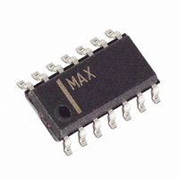
MAX773ESD+ Maxim Integrated Products, MAX773ESD+ Datasheet - Page 8

MAX773ESD+
Manufacturer Part Number
MAX773ESD+
Description
IC CNTRLR DC-DC 8-SOIC
Manufacturer
Maxim Integrated Products
Type
Step-Up (Boost)r
Datasheet
1.MAX770CSA.pdf
(20 pages)
Specifications of MAX773ESD+
Internal Switch(s)
No
Synchronous Rectifier
No
Number Of Outputs
1
Voltage - Output
5V, 12V, 15V, Adj
Current - Output
1A
Frequency - Switching
300kHz
Voltage - Input
3 ~ 16.5 V
Operating Temperature
-40°C ~ 85°C
Mounting Type
Surface Mount
Package / Case
14-SOIC (3.9mm Width), 14-SOL
Power - Output
667mW
Output Voltage
5 V, 12 V, 15 V, 3 V
Output Current
1 A
Input Voltage
3 V to 16.5 V
Mounting Style
SMD/SMT
Maximum Operating Temperature
+ 85 C
Minimum Operating Temperature
- 40 C
Lead Free Status / RoHS Status
Lead free / RoHS Compliant
5V/12V/15V or Adjustable, High-Efficiency,
Low I
The MAX770–MAX773 are BiCMOS, step-up, switch-
mode power-supply controllers that provide preset 5V,
12V, and 15V output voltages, in addition to adjustable-
output operation. Their unique control scheme com-
bines the advantages of pulse-frequency modulation
(low supply current) and pulse-width modulation (high
efficiency with heavy loads), providing high efficiency
over a wide output current range, as well as increased
output current capability over previous PFM devices.
In addition, the external sense resistor and power
transistor allow the user to tailor the output current
capability for each application. Figure 1 shows the
MAX770–MAX773 block diagram.
The MAX770–MAX773 offer three main improvements
over prior pulse-skipping control solutions: 1) the con-
verters operate with tiny (5mm height and less than
9mm diameter) surface-mount inductors due to their
300kHz switching frequency; 2) the current-limited PFM
control scheme allows 87% efficiencies over a wide
range of load currents; and 3) the maximum supply
current is only 110µA.
The MAX773 can be configured to operate from an
internal 6V shunt regulator, allowing very high input/out-
put voltages. Its output can be configured for an
adjustable voltage or for one of three fixed voltages
(5V, 12V, or 15V), and it has a power-fail comparator for
low-battery detection.
All devices have shutdown capability, reducing the
supply current to 5µA max.
Figures 2 and 3 show standard application circuits for
bootstrapped and non-bootstrapped modes. In boot-
strapped mode, the IC is powered from the output
(V
8
_________________________________________________Pin Description (continued)
_______________Detailed Description
MAX770
MAX771
MAX772
OUT
_______________________________________________________________________________________
—
—
—
Bootstrapped/Non-Bootstrapped Modes
, which is connected to V+) and the input voltage
PIN
MAX773
Q
12
13
14
, Step-Up DC-DC Controllers
NAME
EXTH
EXTL
V15
Low-level gate/base drive for external power transistor. Connect to the gate of an external
N-channel MOSFET or to the base of an external NPN transistor.
High-level gate/base drive for external power transistor. Connect to EXTL when using an external
N-channel MOSFET. When using an external NPN transistor, connect a resistor R
EXTH to the base of the NPN to set the maximum base-drive current.
Input sense point for 15V-output operation. Connect V
Leave unconnected for adjustable-output operation
range is 2V to V
the external power transistor is switched from V
ground, providing more switch gate drive and thus
reducing the transistor’s on resistance.
In non-bootstrapped mode, the IC is powered from the
input voltage (V+) and operates with minimum supply
current. In this mode, FB is the output voltage sense
point. Since the voltage swing applied to the gate of the
external power transistor is reduced (the gate swings
from V+ to ground), the power transistor’s on resistance
increases at low input voltages. However, the supply
current is also reduced because V+ is at a lower volt-
age, and because less energy is consumed while
charging and discharging the external MOSFET’s gate
capacitance. The minimum input voltage for the
MAX770–MAX773 is 3V when using external feedback
resistors. With supply voltages below 5V, bootstrapped
mode is recommended.
Note: When using the MAX770/MAX771/MAX772 in
non-bootstrapped mode, there is no preset output
operation because V+ is also the output voltage
sense point for fixed-output operation. External
resistors must be used to set the output voltage.
Use 1% external feedback resistors when operating
in adjustable-output mode (Figures 2c, 2d, 3b, 3d, 3e)
to achieve an overall output voltage accuracy of ±5%.
The MAX773 can be operated in non-bootstrapped
mode without using external feedback resistors
because V+ does not act as the output voltage sense
point with preset-output operation. To achieve high-
est efficiency, operate in bootstrapped mode when-
ever possible.
The MAX773 has an internal 6V shunt regulator that
allows the device to step up from very high input
voltages (Figure 4).
FUNCTION
MAX773 Shunt-Regulator Operation
OUT
OUT
. The voltage applied to the gate of
to V15 for 15V-output operation.
BASE
from
OUT
to


