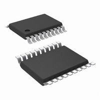
LM3100MH/NOPB National Semiconductor, LM3100MH/NOPB Datasheet - Page 12

LM3100MH/NOPB
Manufacturer Part Number
LM3100MH/NOPB
Description
IC REG SIMPLE SW 1.5A 20-TSSOP
Manufacturer
National Semiconductor
Series
PowerWise®, SIMPLE SWITCHER®r
Type
Step-Down (Buck)r
Datasheet
1.LM3100MHXNOPB.pdf
(18 pages)
Specifications of LM3100MH/NOPB
Internal Switch(s)
Yes
Synchronous Rectifier
Yes
Number Of Outputs
1
Voltage - Output
0.8 ~ 7 V
Current - Output
1.5A
Frequency - Switching
1MHz
Voltage - Input
4.5 ~ 36 V
Operating Temperature
-40°C ~ 125°C
Mounting Type
Surface Mount
Package / Case
20-TSSOP Exposed Pad, 20-eTSSOP, 20-HTSSOP
Dc To Dc Converter Type
Step Down
Pin Count
20
Input Voltage
36V
Output Voltage
0.8 to 7V
Switching Freq
1000KHz
Output Current
1.5A
Efficiency
86%
Package Type
TSSOP EP
Output Type
Adjustable
Switching Regulator
Yes
Mounting
Surface Mount
Input Voltage (min)
4.5V
Operating Temp Range
-40C to 125C
Operating Temperature Classification
Automotive
For Use With
LM3100EVAL - BOARD EVAL LM3100
Lead Free Status / RoHS Status
Lead free / RoHS Compliant
Power - Output
-
Lead Free Status / Rohs Status
Compliant
Other names
*LM3100MH
*LM3100MH/NOPB
LM3100MH
*LM3100MH/NOPB
LM3100MH
www.national.com
nal pull-up resistor. For all cases, this voltage must be limited
not to exceed 7V.
FIGURE 1. Shutdown Implementation
FIGURE 2. Inductor Current - Current Limit Operation
20174704
12
Current Limit
Current limit detection occurs during the off-time by monitor-
ing the re-circulating current through the low-side syn-
chronous switch. Referring to Functional Block Diagram,
when the buck switch is turned off, inductor current flows
through the load, into PGND, and through the internal low-
side synchronous switch. If that current exceeds 1.9A the
current limit comparator toggles, forcing a delay to the start of
the next on-time period. The next cycle starts when the re-
circulating current falls back below 1.9A and the voltage at FB
is below 0.8V. The inductor current is monitored during the
low-side switch on-time. As long as the overload condition
persists and the inductor current exceeds 1.9A, the high-side
switch will remain inhibited. The operating frequency is lower
during an over-current due to longer than normal off-times.
Figure 2
inductor current is equal to the output current, I
state. When an overload occurs, the inductor current will in-
crease until it exceeds the current limit threshold, 1.9A. Then
the control keeps the high-side switch off until the inductor
current ramps down below 1.9A. Within each on-time period,
the current ramps up an amount equal to:
During this time the LM3100 is in a constant current mode,
with an average load current (I
illustrates an inductor current waveform, the average
OCL
) equal to 1.9A +ΔI/2.
20174705
OUT
in steady
(6)


