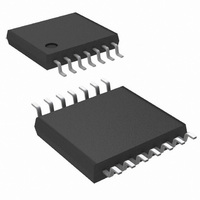
LM2744MTC/NOPB National Semiconductor, LM2744MTC/NOPB Datasheet - Page 12

LM2744MTC/NOPB
Manufacturer Part Number
LM2744MTC/NOPB
Description
IC REG SYNC BUCK N-CH 14-TSSOP
Manufacturer
National Semiconductor
Series
PowerWise®r
Type
Step-Down (Buck)r
Datasheet
1.LM2744MTCXNOPB.pdf
(24 pages)
Specifications of LM2744MTC/NOPB
Internal Switch(s)
No
Synchronous Rectifier
Yes
Number Of Outputs
1
Voltage - Output
0.5 ~ 1.5 V
Current - Output
20A
Frequency - Switching
50kHz ~ 1MHz
Voltage - Input
1 ~ 16 V
Operating Temperature
-40°C ~ 125°C
Mounting Type
Surface Mount
Package / Case
14-TSSOP
For Use With
LM2744EVAL - BOARD EVALUATION LM2744
Lead Free Status / RoHS Status
Lead free / RoHS Compliant
Power - Output
-
Other names
*LM2744MTC
*LM2744MTC/NOPB
LM2744MTC
*LM2744MTC/NOPB
LM2744MTC
www.national.com
goes high. This bootstrap voltage is usually supplied from a
local charge pump structure. But looking at the Typical Appli-
cation schematic, this also means that the difference voltage
V
charges up to, must be always greater than the maximum tol-
erance limit of the threshold voltage of the upper MOSFET.
Here V
diode D1. This therefore may place restrictions on the mini-
mum input voltage and/or type of MOSFET used.
The most basic charge bootstrap pump circuit can be built
using one Schottky diode and a small capacitor, as shown in
Figure 7. The capacitor C
voltage between the top MOSFET gate and source to control
the device even when the top MOSFET is on and its source
has risen up to the input voltage level. The charge pump cir-
cuitry is fed from V
3.0V to 6.0V. Using this basic method the voltage applied to
the gates of both high-side and low-side MOSFETs is V
V
the gate drives will get at least 4.0V of drive voltage during
the worst case of V
level MOSFETs generally specify their on-resistance at V
= 4.5V. When V
could go as low as 2.5V. Logic level MOSFETs are not guar-
anteed to turn on, or may have much higher on-resistance at
2.5V. Sub-logic level MOSFETs, usually specified at V
2.5V, will work, but are more expensive, and tend to have
higher on-resistance. The circuit in Figure 7 works well for
input voltages ranging from 1V up to 16V and V
because the drive voltage depends only on V
Note that the LM2744 can be paired with a low cost linear
regulator like the LP8340 to run from a single input rail be-
tween 6.0 and 16V. The 5V output of the linear regulator
powers both the V
cient drive for logic level MOSFETs. An example of this circuit
is shown in Figure 8.
CC
D
. This method works well when V
- V
FIGURE 7. Basic Charge Pump (Bootstrap)
D1
D1
is the forward voltage drop across the bootstrap
, which is the voltage the bootstrap capacitor
CC
CC
= 3.3V±10%, the gate drive at worst case
CC
CC-MIN
and the bootstrap circuit, providing effi-
, which can operate over a range from
= 4.5V and V
BOOT
serves to maintain enough
CC
is 5V±10%, because
D-MAX
CC
CC
= 0.5V. Logic
.
= 5V ±10%,
20106012
GS
CC
GS
=
-
12
Figure 9 shows a second possibility for bootstrapping the
MOSFET drives using a doubler. This circuit provides an
equal voltage drive of V
and low-side MOSFET drives. This method should only be
used in circuits that use 3.3V for both V
V
both high-side and low-side gates will have at least 4.5V of
drive. The power dissipation of the gate drive circuitry is di-
rectly proportional to gate drive voltage, hence the thermal
limits of the LM2744 IC will quickly be reached if this circuit is
used with V
All the gate drive circuits shown in the above figures typically
use 100nF ceramic capacitors in the bootstrap locations.
POWER GOOD SIGNAL
The Power Good signal is an OR-gated flag which takes into
account both output overvoltage and undervoltage condi-
tions. If the feedback pin (FB) voltage is 18% above its nom-
inal value or falls 28% below that value the Power Good flag
goes low. The Power Good flag can be used to signal other
IN
= V
FIGURE 9. Charge Pump with Added Gate Drive
FIGURE 8. LP8340 Feeding Basic Charge Pump
CC
= 3.0V (10% lower tolerance on 3.3V) and V
CC
or V
IN
voltages over 5V.
CC
- 3V
D
+ V
IN
CC
to both the high-side
and V
IN
20106019
. Even with
20106013
D
= 0.5V


