IP1202TR International Rectifier, IP1202TR Datasheet - Page 2
IP1202TR
Manufacturer Part Number
IP1202TR
Description
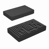
DUAL OUTPUT 2PH PWR BLOCK 198BGA
Manufacturer
International Rectifier
Series
iPOWIR™r
Type
Step-Down (Buck)r
Datasheet
1.IP1202.pdf
(29 pages)
Specifications of IP1202TR
Internal Switch(s)
Yes
Synchronous Rectifier
Yes
Number Of Outputs
2
Voltage - Output
0.8 ~ 5 V
Current - Output
30A
Frequency - Switching
200kHz ~ 400kHz
Voltage - Input
5.5 ~ 13.2 V
Operating Temperature
-40°C ~ 125°C
Mounting Type
Surface Mount
Package / Case
198-BGA (161 bumps)
Power - Output
7W
Input Voltage
13.2V
Output Current
15A
Output Voltage
5V
No. Of Outputs
2
No. Of Pins
198
Operating Temperature Range
-40°C To +125°C
Termination Type
SMD
Supply Voltage Min
5.5V
Rohs Compliant
No
Filter Terminals
SMD
Frequency
460kHz
Package
BGA - 15.5 x 9.25
Circuit
Single Output or Dual Ch
Iout (a)
30
Switch Freq (khz)
200 - 400
Input Range (v)
5.5 - 13.2
Output Range (v)
0.8 - 5.0
Ocp Otp Uvlo Pre-bias Soft Start And
OVP + OCP + OTP and Soft Start
Pbf
PbF Option Available
Lead Free Status / RoHS Status
Contains lead / RoHS non-compliant
Available stocks
Company
Part Number
Manufacturer
Quantity
Price
Company:

Part Number:
IP1202TR
Manufacturer:
EPSON
Quantity:
13 929
Company:
Part Number:
IP1202TR
Manufacturer:
International Rectifier
Quantity:
10 000
Company:
Part Number:
IP1202TRPBF
Manufacturer:
International Rectifier
Quantity:
10 000


iP1202
Absolute Maximum Ratings
Recommended Operating Conditions
Electrical Specifications @ V
2
Parameter
Input Voltage Range
Output RMS Current Per Channel
Output Voltage Range
Parameter
Power Loss
Over Current Shutdown
HICCUP duty cycle
Soft Start Time
Reference Voltage
V
Error Amplifier 2 input offset
voltage
FB1/FB2 Input bias current
Error Amplifier
source/sink Current
Error Amplifier
Transconductance
Output Overvoltage Shutdown
Threshold
OVP Fault Propagation Delay
PGOOD Trip Threshold
PGOOD Output Low Voltage
Parameter
V
Feedback
Output Overvoltage Sense
PGOOD
ENABLE
Soft Start
Vp-ref
HICCUP
SYNC
Output RMS Current Per Channel
Block Temperature
OUT
IN
Accuracy
All specifications @ 25°C (unless otherwise specified)
IN
VFB1
VFB1/VFB2
= 12V
V
V
V
V
SS1/SS2
HICCUP
Symbol
Symbol
Symbol
D
g
Iout
Iout
Th_PGOOD
LO_PGOOD
OUT_ACC1
OUT_ACC2
P
m1,
OVP
V
V
V
T
HICCUP
I
I
t
V
V
I
LOSS
t
ERR
OVP
S
BFB
OC
OUT
SS
REF
OS2
BLK
/VFB2
IN
IN
VSW
VSW
g
m2
S
Min
-0.3
-0.3
-0.3
-0.3
-0.3
-0.3
-0.3
-0.3
-0.3
Min
Min
-2.5
-40
5.5
0.8
0.8
-3
-4
-
-
-
-
-
-
-
-
-
-
-
-
-
-
1.15 x V
0.85 x V
2000
0.25
Typ
Typ
-0.1
Typ
7.0
0.8
25
60
25
5
5
-
-
-
-
-
-
-
-
-
-
-
-
-
-
-
-
-
-
-
OUT
OUT
Max
8.75
Max
Max
13.2
125
2.5
5.0
3.3
15
15
15
15
15
15
11
6
6
6
6
6
3
4
-
-
-
-
-
-
-
-
-
µmho
Units
Units
Units
mV
ms
µA
µA
°C
µs
W
%
%
A
V
V
V
V
V
A
A
A
V
2 Independent outputs. See Fig. 3
Capable of start up over full temperature
range. See Note 1.
f
V
V
HICCUP pin pulled Low
HICCUP pin pulled high, output short
circuited.
V
C
T
V
T
V
V
current share accuracy in parallel
configuration. R
Iout= 30A. See Fig. 15
See OVP note in Design Guidelines
Output forced to 1.125Vref
FB1 or FB2 ramping down
I
2 Independent outputs
T
2 Independent outputs
T
heatsink. See Fig. 3
For V
For V
SW =
f
SINK
SW
BLK
BLK
OUT1
IN
IN
SS1
IN
IN
IN
Conditions
PCB
PCB
Conditions
Conditions
= 12V, V
= 12V, V
= 12V, V
= 12V, V
= 12V, V
=2mA
= 300KHz, R
= C
300kHz, V
= -40°C to 125°C, See Note 1.
= 0°C to 125°C, See Note 1.
= T
= 90°C, T
IN
IN
= V
= 12V
= 5.5V
SS2
CASE
OUT2
=0.1µF
OUT
OUT
OUT
OUT
OUT
= 90°C. See Fig. 3
= 1.5V, I
CASE
IN
= 1.5V
= 1.5V
= 1.5V
shunt1
= 1.5V,
= 1.5V, specified for
OCSET
= 12V, T
= no airflow, no
= R
www.irf.com
OUT1
= 51.1kΩ
shunt2
BLK
= I
= 25°C
=5mΩ ,
OUT2
= 15A
Related parts for IP1202TR
Image
Part Number
Description
Manufacturer
Datasheet
Request
R

Part Number:
Description:
DUAL OUTPUT 2PH PWR BLOCK 198BGA
Manufacturer:
International Rectifier
Datasheet:

Part Number:
Description:
SCHOTTKY RECTIFIER
Manufacturer:
International Rectifier Corp.
Datasheet:
Part Number:
Description:
SCHOTTKY RECTIFIER
Manufacturer:
International Rectifier Corp.
Datasheet:
Part Number:
Description:
SCHOTTKY RECTIFIER
Manufacturer:
International Rectifier Corp.
Datasheet:
Part Number:
Description:
SCHOTTKY RECTIFIER
Manufacturer:
International Rectifier Corp.
Datasheet:
Part Number:
Description:
SCHOTTKY RECTIFIER
Manufacturer:
International Rectifier Corp.
Datasheet:
Part Number:
Description:
SCHOTTKY RECTIFIER
Manufacturer:
International Rectifier Corp.
Datasheet:
Part Number:
Description:
SCHOTTKY RECTIFIER
Manufacturer:
International Rectifier Corp.
Datasheet:
Part Number:
Description:
SCHOTTKY RECTIFIER
Manufacturer:
International Rectifier Corp.
Datasheet:
Part Number:
Description:
SCHOTTKY RECTIFIER
Manufacturer:
International Rectifier Corp.
Datasheet:
Part Number:
Description:
SCHOTTKY RECTIFIER
Manufacturer:
International Rectifier Corp.
Datasheet:
Part Number:
Description:
SCHOTTKY RECTIFIER
Manufacturer:
International Rectifier Corp.
Datasheet:
Part Number:
Description:
SCHOTTKY RECTIFIER
Manufacturer:
International Rectifier Corp.
Datasheet:
Part Number:
Description:
SCHOTTKY RECTIFIER
Manufacturer:
International Rectifier Corp.
Datasheet:
Part Number:
Description:
SCHOTTKY RECTIFIER
Manufacturer:
International Rectifier Corp.
Datasheet: