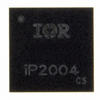
IP2004TR International Rectifier, IP2004TR Datasheet - Page 12

IP2004TR
Manufacturer Part Number
IP2004TR
Description
IC PWR BLOCK MULTIPHASE 40A LGA
Manufacturer
International Rectifier
Series
iPOWIR™r
Type
Step-Down (Buck)r
Datasheet
1.IP2004TR.pdf
(15 pages)
Specifications of IP2004TR
Internal Switch(s)
Yes
Synchronous Rectifier
Yes
Number Of Outputs
1
Voltage - Output
0.8 ~ 8 V
Current - Output
40A
Frequency - Switching
250kHz ~ 1.5MHz
Voltage - Input
3.3 ~ 13.2 V
Operating Temperature
-40°C ~ 125°C
Mounting Type
Surface Mount
Package / Case
Power Block (LGA)
Power - Output
7.4W
Lead Free Status / RoHS Status
Lead free / RoHS Compliant
PCB Layout Guidelines
The following guidelines are recommended to reduce the parasitic values and optimize overall performance.
Page 12 of 15
•
•
•
•
•
•
All pads on the iP2004 footprint design need to be Solder-mask defined (see
International Rectifier application notes AN1028 and AN1029 for further footprint design guidance.
Place as many vias around the Power pads (V
performance.
A minimum of six 10µF, X5R, 16V ceramic capacitors per iP2004 are needed for greater than 25A
operation. This will result in the lowest loss due to input capacitor ESR.
Placement of the ceramic input capacitors is critical to optimize switching performance. In cases where
there is a heatsink on the case of iP2004, place all six ceramic capacitors right underneath the iP2004
footprint (see Bottom Component Layer). In cases where there is not heatsink, C1 and C6 on the
bottom layer may be moved to the C1x and C6x locations (respectively) on the top component layer
(see Top Component Layer). In both cases, C2 – C5 need to be placed right underneath the iP2004
PCB footprint.
Dedicate at least two layer to for PGND only
Duplicate the Power Nodes on multiple layers (refer to AN1029).
Figure 15 Top & Bottom Component and Via Placement (Topside, Transparent view down)
o
Vias in between the different power pads may overlap the pad opening and solder mask edge
without the need to plug the via hole. Vias with a 13mil drill hole and 25mil capture pad were
used in this example.
www.irf.com
IN
, V
SW
, and P
GND
) for both electrical and optimal thermal
Data Sheet No. PD60322
12/22/2007
Figure 14
iP2004
). Also refer to


