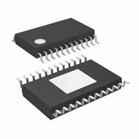
LTC3862HFE-1#TRPBF Linear Technology, LTC3862HFE-1#TRPBF Datasheet - Page 30

LTC3862HFE-1#TRPBF
Manufacturer Part Number
LTC3862HFE-1#TRPBF
Description
IC CTRLR DC/DC STPUP 24-TSSOP
Manufacturer
Linear Technology
Type
Step-Up (Boost)r
Datasheet
1.LTC3862EFE-1PBF.pdf
(40 pages)
Specifications of LTC3862HFE-1#TRPBF
Internal Switch(s)
No
Synchronous Rectifier
No
Number Of Outputs
1
Voltage - Output
1.22 ~ 200 V
Current - Output
50mA
Frequency - Switching
300kHz
Voltage - Input
4 ~ 36 V
Operating Temperature
-40°C ~ 150°C
Mounting Type
Surface Mount
Package / Case
24-TSSOP Exposed Pad, 24-eTSSOP, 24-HTSSOP
Lead Free Status / RoHS Status
Lead free / RoHS Compliant
Power - Output
-
LTC3862-1
APPLICATIONS INFORMATION
For the bulk capacitance, which we assume contributes
1% to the total output ripple, the minimum required ca-
pacitance is approximately:
For many designs it will be necessary to use one type of
capacitor to obtain the required ESR, and another type
to satisfy the bulk capacitance. For example, using a
low ESR ceramic capacitor can minimize the ESR step,
while an electrolytic capacitor can be used to supply the
required bulk C.
The voltage rating of the output capacitor must be greater
than the maximum output voltage, with suffi cient derating
to account for the maximum capacitor temperature.
Because the ripple current in the output capacitor is a
square wave, the ripple current requirements for this
capacitor depend on the duty cycle, the number of phases
and the maximum output current. Figure 23 illustrates the
normalized output capacitor ripple current as a function of
duty cycle. In order to choose a ripple current rating for
the output capacitor, fi rst establish the duty cycle range,
based on the output voltage and range of input voltage.
Referring to Figure 23, choose the worst-case high nor-
malized ripple current, as a percentage of the maximum
load current.
30
C
OUT
≥
0.01• n • V
I
O(MAX)
OUT
• f
Figure 23: Normalized Output Capacitor
Ripple Current (RMS) for a Boost Converter
3.25
3.00
2.75
2.50
2.25
2.00
1.75
1.50
1.25
1.00
0.75
0.50
0.25
0
0.1
0.2
DUTY CYCLE OR (1-V
0.3
0.4
1-PHASE
0.5
The output ripple current is divided between the various
capacitors connected in parallel at the output voltage.
Although ceramic capacitors are generally known for low
ESR (especially X5R and X7R), these capacitors suffer
from a relatively high voltage coeffi cient. Therefore, it is
not safe to assume that the entire ripple current fl ows in
the ceramic capacitor. Aluminum electrolytic capacitors are
generally chosen because of their high bulk capacitance,
but they have a relatively high ESR. As a result, some
amount of ripple current will fl ow in this capacitor. If the
ripple current fl owing into a capacitor exceeds its RMS
rating, the capacitor will heat up, reducing its effective
capacitance and adversely affecting its reliability. After
the output capacitor confi guration has been determined
using the equations provided, measure the individual
capacitor case temperatures in order to verify good
thermal performance.
Input Capacitor Selection
The input capacitor voltage rating in a boost converter
should comfortably exceed the maximum input voltage.
Although ceramic capacitors can be relatively tolerant of
overvoltage conditions, aluminum electrolytic capacitors
are not. Be sure to characterize the input voltage for any
possible overvoltage transients that could apply excess
stress to the input capacitors.
0.6
IN
/V
2-PHASE
0.7
OUT
)
0.8
38621 F23
0.9
38621f


