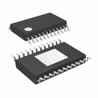
LTC3862IFE-1#PBF Linear Technology, LTC3862IFE-1#PBF Datasheet - Page 31

LTC3862IFE-1#PBF
Manufacturer Part Number
LTC3862IFE-1#PBF
Description
IC CTRLR DC/DC STPUP 24-TSSOP
Manufacturer
Linear Technology
Type
Step-Up (Boost)r
Datasheet
1.LTC3862EFE-1PBF.pdf
(40 pages)
Specifications of LTC3862IFE-1#PBF
Internal Switch(s)
No
Synchronous Rectifier
No
Number Of Outputs
1
Voltage - Output
1.22 ~ 200 V
Current - Output
50mA
Frequency - Switching
300kHz
Voltage - Input
4 ~ 36 V
Operating Temperature
-40°C ~ 125°C
Mounting Type
Surface Mount
Package / Case
24-TSSOP Exposed Pad, 24-eTSSOP, 24-HTSSOP
Lead Free Status / RoHS Status
Lead free / RoHS Compliant
Power - Output
-
Available stocks
Company
Part Number
Manufacturer
Quantity
Price
APPLICATIONS INFORMATION
The value of the input capacitor is a function of the
source impedance, and in general, the higher the source
impedance, the higher the required input capacitance.
The required amount of input capacitance is also greatly
affected by the duty cycle. High output current applica-
tions that also experience high duty cycles can place great
demands on the input supply, both in terms of DC current
and ripple current.
The input ripple current in a multi-phase boost converter
is relatively low (compared with the output ripple current),
because this current is continuous and is being divided
between two or more inductors. Nonetheless, signifi cant
stress can be placed on the input capacitor, especially
in high duty cycle applications. Figure 24 illustrates the
normalized input ripple current, where:
I
Figure 24. Normalized Input Peak-to-Peak Ripple Current
NORM
=
1.00
0.90
0.80
0.70
0.60
0.50
0.40
0.30
0.20
0.10
L • f
0
V
0
IN
0.2
1-PHASE
0.4
DUTY CYCLE
0.6
2-PHASE
0.8
38621 F24
1.0
A Design Example
Consider the LTC3862-1 application circuit is shown in
Figure 25a. The output voltage is 72V and the input voltage
range is 8.5V to 36V. The maximum output current is 1.5A
when the input voltage is 24V and 2A at an input of 32V.
Below 32V, current limit will linearly reduce the maximum
load to 0.5A at 8.5V input voltage (see Figure 25b).
1. The duty cycle range (where 1.5A is available at the
2. The operating frequency is chosen to be 300kHz so
3. The minimum on-time for this application operating
output) is:
the period is 3.33μs. From Figure 6, the resistor from
the FREQ pin to ground is 45.3k.
in CCM is:
The maximum DC input current is:
D
D
I
t
IN(MAX)
ON(MIN)
MAX
MIN
=
=
=
=
=
72V + 0.5V – 36V
V
72V + 0.5V – 24V
1– D
1
I
O
f
O(MAX)
72V + 0.5V
•
V
72V + 0.5V – 36V
+ V
72V + 0.5V
O
MAX
V
+ V
72V + 0.5V
F
O
– V
+ V
F
=
V
IN
1– 0.669
F
O
– V
1.5A
+ V
IN(MAX)
F
LTC3862-1
= 50.3%
= 66.9%
= 4.5A
= 1.678µs
=
300kHz
1
31
38621f
•


