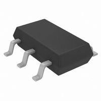
LTC3400ES6#TRM Linear Technology, LTC3400ES6#TRM Datasheet

LTC3400ES6#TRM
Specifications of LTC3400ES6#TRM
Available stocks
Related parts for LTC3400ES6#TRM
LTC3400ES6#TRM Summary of contents
Page 1
... EMI concerns by damping the inductor in discontinuous mode, and the devices feature low shutdown current of under 1 A. Both devices are available in the low profile (1mm) SOT-23 package. , LTC, LT and Burst Mode are registered trademarks of Linear Technology Corporation. ThinSOT is a trademark of Linear Technology Corporation OUT 5 3 ...
Page 2
LTC3400/LTC3400B ABSOLUTE AXI U RATI GS (Note 1) V Voltage ................................................. – 0. Voltage ................................................. – 0. SHDN, FB Voltage ....................................... – 0. ........................................................... – 0. ...
Page 3
W U TYPICAL PERFOR A CE CHARACTERISTICS Output Load Burst Mode Threshold 4 3. OUT OUT 10 0 0.9 1.5 2.1 2.7 3.3 ...
Page 4
LTC3400/LTC3400B CTIO S SW (Pin 1): Switch Pin. Connect inductor between SW and V . Optional Schottky diode is connected between IN SW and V . Keep these PCB trace lengths as short and OUT ...
Page 5
U OPERATIO The LTC3400/LTC3400B are 1.2MHz, synchronous boost converters housed in a 6-lead ThinSOT package. Able to operate from an input voltage below 1V, the devices feature fixed frequency, current mode PWM control for exceptional line and load regulation. With ...
Page 6
LTC3400/LTC3400B U OPERATIO burst threshold, the LTC3400 will resume continuous PWM operation seamlessly. Referring to the Block Dia- gram, an optional capacitor (C ) between V FF some circumstances can reduce the peak-to-peak V ripple and input quiescent current during ...
Page 7
U U APPLICATIO S I FOR ATIO The inductor current ripple is typically set for 20% to 40% of the maximum inductor current (I ferrite core inductor materials reduce frequency depen- dent power losses compared to cheaper powdered iron types, ...
Page 8
LTC3400/LTC3400B U TYPICAL APPLICATIO S + SINGLE AA CELL OFF ON D1: CENTRAL SEMI CMDSH2-3 L1: COILCRAFT DS1608-472 8 Single Cell to 3.3V Synchronous Boost Converter with Load Disconnect in Shutdown ...
Page 9
U TYPICAL APPLICATIO S + LITHIUM CELL D1: PHILIPS PMEG2010EA L1: SUMIDA CMD4D06-4R7 C1, C2: TAIYO YUDEN JMK212BJ475MG Single Lithium Cell to 5V, 250mA OPTIONAL 2 SNUBBER 1nF ...
Page 10
LTC3400/LTC3400B U TYPICAL APPLICATIO S Single Cell AA Cell to 3V Synchronous Boost Converter + SINGLE AA CELL D1, D2: ZETEX FMND7000 DUAL DIODE L1: COILCRAFT DS1608-472 4 4 ...
Page 11
... MOLD FLASH SHALL NOT EXCEED 0.254mm 6. JEDEC PACKAGE REFERENCE IS MO-193 Information furnished by Linear Technology Corporation is believed to be accurate and reliable. However, no responsibility is assumed for its use. Linear Technology Corporation makes no represen- tation that the interconnection of its circuits as described herein will not infringe on existing patent rights. U ...
Page 12
... OUT as Low as 1.1V 30mA from Single Cell Shutdown Current Low for Gate Drive CC = 2.6V to 16V 450mA from 3.3V Input IN as Low as 1.5V 0.5V to 4.5V, IN (min): 2.4V to 5.25V QFN OUT Q LT/TP 0903 1K REV A • PRINTED IN USA LINEAR TECHNOLOGY CORPORATION 2001 3400fa ...


