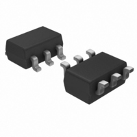
LTC1872ES6#TRPBF Linear Technology, LTC1872ES6#TRPBF Datasheet - Page 9

LTC1872ES6#TRPBF
Manufacturer Part Number
LTC1872ES6#TRPBF
Description
IC DC/DC CONTRLR STEP-UP SOT23-6
Manufacturer
Linear Technology
Type
Step-Up (Boost)r
Datasheet
1.LTC1872ES6TR.pdf
(12 pages)
Specifications of LTC1872ES6#TRPBF
Internal Switch(s)
No
Synchronous Rectifier
No
Number Of Outputs
1
Voltage - Output
0.8 ~ 36 V
Frequency - Switching
550kHz
Voltage - Input
2.5 ~ 9.8 V
Operating Temperature
-65°C ~ 150°C
Mounting Type
Surface Mount
Package / Case
SOT-23-6
Lead Free Status / RoHS Status
Lead free / RoHS Compliant
Current - Output
-
Power - Output
-
Available stocks
Company
Part Number
Manufacturer
Quantity
Price
APPLICATIONS
For most applications, an 80k resistor is suggested for R1.
To prevent stray pickup, locate resistors R1 and R2 close
to LTC1872.
Efficiency Considerations
The efficiency of a switching regulator is equal to the
output power divided by the input power times 100%. It is
often useful to analyze individual losses to determine what
is limiting the efficiency and which change would produce
the most improvement. Efficiency can be expressed as:
where 1, 2, etc. are the individual losses as a percent-
age of input power.
Although all dissipative elements in the circuit produce
losses, four main sources usually account for most of the
losses in LTC1872 circuits: 1) LTC1872 DC bias current,
2) MOSFET gate charge current, 3) I
voltage drop of the output diode.
1. The V
Efficiency = 100% – ( 1 + 2 + 3 + ...)
electrical characteristics, that excludes MOSFET driver
and control currents. V
which increases with V
IN
current is the DC supply current, given in the
U
INFORMATION
IN
U
IN
current results in a small loss
.
W
2
R losses and 4)
U
2. MOSFET gate charge current results from switching
3. I
4. The output diode is a major source of power loss at
5. Transition losses apply to the external MOSFET and
Other losses, including C
losses, and inductor core losses, generally account for
less than 2% total additional loss.
the gate capacitance of the power MOSFET. Each time
a MOSFET gate is switched from low to high to low
again, a packet of charge, dQ, moves from V
ground. The resulting dQ/dt is a current out of V
which is typically much larger than the contoller’s DC
supply current. In continuous mode, I
MOSFET, inductor and current sense resistor. The
MOSFET R
average output current squared can be summed with
I
sense resistor.
high currents. The diode loss is calculated by multiply-
ing the forward voltage by the load current.
increase at higher operating frequencies and input
voltages. Transition losses can be estimated from:
Transition Loss = 2(V
2
2
R losses are predicted from the DC resistances of the
R losses in the inductor ESR in series with the current
DS(ON)
multiplied by duty cycle times the
IN
IN
)
2
I
IN(MAX)
and C
OUT
C
RSS
GATECHG
ESR dissipative
LTC1872
(f)
= f(Qp).
IN
9
to
IN


