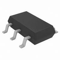
LTC1772BES6#TRPBF Linear Technology, LTC1772BES6#TRPBF Datasheet - Page 10

LTC1772BES6#TRPBF
Manufacturer Part Number
LTC1772BES6#TRPBF
Description
IC CTRLR DC/DC S-DWN SOT23-6
Manufacturer
Linear Technology
Type
Step-Down (Buck)r
Datasheet
1.LTC1772BES6TRMPBF.pdf
(16 pages)
Specifications of LTC1772BES6#TRPBF
Internal Switch(s)
No
Synchronous Rectifier
No
Number Of Outputs
1
Voltage - Output
0.8 ~ 9.8 V
Current - Output
1A
Frequency - Switching
550kHz
Voltage - Input
2.5 ~ 9.8 V
Operating Temperature
-40°C ~ 85°C
Mounting Type
Surface Mount
Package / Case
TSOT-23-6, TSOT-6
Lead Free Status / RoHS Status
Lead free / RoHS Compliant
Power - Output
-
Available stocks
Company
Part Number
Manufacturer
Quantity
Price
APPLICATIONS INFORMATION
LTC1772B
size or height requirements in the design. Due to the high
operating frequency of the LTC1772B, ceramic capacitors
can also be used for C
if there is any question.
The selection of C
series resistance (ESR). Typically, once the ESR require-
ment is satisfi ed, the capacitance is adequate for fi ltering.
The output ripple (ΔV
where f is the operating frequency, C
capacitance and I
tor. The output ripple is highest at maximum input voltage
since ΔI
Manufacturers such as Nichicon, United Chemicon and
Sanyo should be considered for high performance through-
hole capacitors. The OS-CON semiconductor dielectric
capacitor available from Sanyo has the lowest ESR (size)
product of any aluminum electrolytic at a somewhat higher
price. Once the ESR requirement for C
the RMS current rating generally far exceeds the I
requirement.
Low Supply Operation
Although the LTC1772B can function down to approxi-
mately 2.0V, the maximum allowable output current is
reduced when V
the amount of change as the supply is reduced down to
2V. Also shown in Figure 4 is the effect of V
V
Setting Output Voltage
The regulated output voltage is determined by:
For most applications, an 80k resistor is suggested for
R1. To prevent stray pickup, locate resistors R1 and R2
close to LTC1772B.
10
IN
V
goes below 2.3V.
OUT
V
OUT
L
= 0.8 1+
increases with input voltage.
I
RIPPLE
IN
RIPPLE
R2
OUT
R1
decreases below 3V. Figure 4 shows
ESR +
IN
OUT
is driven by the required effective
. Always consult the manufacturer
is the ripple current in the induc-
) is approximated by:
4fC
1
OUT
OUT
OUT
has been met,
is the output
IN
on V
RIPPLE(P-P)
REF
as
Effi ciency Considerations
The effi ciency of a switching regulator is equal to the output
power divided by the input power times 100%. It is often
useful to analyze individual losses to determine what is
limiting the effi ciency and which change would produce
the most improvement. Effi ciency can be expressed as:
where η1, η2, etc. are the individual losses as a percent-
age of input power.
Although all dissipative elements in the circuit produce
losses, four main sources usually account for most of
the losses in LTC1772B circuits: 1) LTC1772B DC bias
Effi ciency = 100% – (η1 + η2 + η3 + ...)
Figure 4. Line Regulation of V
105
100
95
90
85
80
75
LTC1772B
Figure 5. Setting Output Voltage
2.0
V
FB
2.2
3
INPUT VOLTAGE (V)
V
V
2.4
REF
ITH
2.6
R2
R1
REF
2.8
and V
1772 F04
V
OUT
1772 F03
3.0
ITH
1772bfa


