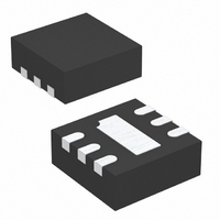
LTC3240EDC-2.5#TRPBF Linear Technology, LTC3240EDC-2.5#TRPBF Datasheet - Page 3

LTC3240EDC-2.5#TRPBF
Manufacturer Part Number
LTC3240EDC-2.5#TRPBF
Description
IC DC/DC CONV 2.5V 6-DFN
Manufacturer
Linear Technology
Type
Step-Down (Buck), Step-Up (Boost), Switched Capacitor (Charge Pump)r
Datasheet
1.LTC3240EDC-3.3TRMPBF.pdf
(12 pages)
Specifications of LTC3240EDC-2.5#TRPBF
Internal Switch(s)
Yes
Synchronous Rectifier
No
Number Of Outputs
1
Voltage - Output
2.5V
Current - Output
150mA
Frequency - Switching
1.2MHz
Voltage - Input
1.8 ~ 5.5 V
Operating Temperature
-40°C ~ 85°C
Mounting Type
Surface Mount
Package / Case
6-DFN
Lead Free Status / RoHS Status
Lead free / RoHS Compliant
Power - Output
-
Available stocks
Company
Part Number
Manufacturer
Quantity
Price
Part Number:
LTC3240EDC-2.5#TRPBFLTC3240EDC-2.5#PBF
Manufacturer:
LINEAR/凌特
Quantity:
20 000
ELECTRICAL CHARACTERISTICS
temperature range, otherwise specifi cations are at T
Note 1: Stresses beyond those listed under Absolute Maximum Ratings
may cause permanent damage to the device. Exposure to any Absolute
Maximum Rating condition for extended periods may affect device
reliability and lifetime.
Note 2: The LTC3240-3.3/LTC3240-2.5 are guaranteed to meet
performance specifi cations from 0°C to 85°C. Specifi cations over the
SYMBOL
R
TYPICAL PERFOR A CE CHARACTERISTICS
unless otherwise noted)
OL
1000
900
800
700
600
500
400
1.8
1.6
1.4
1.2
1.0
0.8
0.6
1.8
1.6
Oscillator Frequency vs Supply
Voltage (Doubler Mode)
Start-Up Time vs Supply Voltage
1.8
2.2
2
SUPPLY VOLTAGE (V)
2.2
PARAMETER
Effective Open-Loop
Output Resistance
(Note 3)
2.6
2.4
V
LTC3240-3.3
LTC3240-2.5
IN
2.6
(V)
25°C
3.0
2.8
I
3
LOAD
–40°C
W
85°C
3.4
3.2
= 50mA
3.4
3240 G01
3240 G04
U
3.8
3.6
3.40
3.30
3.25
3.20
3.35
1.0
0.8
0.6
0.4
0.2
CONDITIONS
Doubler Mode
V
V
0
IN
IN
1.80
A
0
⎯ S ⎯ H ⎯ D ⎯ N Threshold Voltage
vs Supply Voltage
Load Regulation (LTC3240-3.3)
= 1.8V, V
= 1.8V, V
= 25°C, ⎯ S ⎯ H ⎯ D ⎯ N = V
2.30 2.80
The
30
OUT
OUT
SUPPLY VOLTAGE (V)
LOAD CURRENT (mA)
●
3.30
= 3V
= 2.25V
denotes the specifi cations which apply over the full operating
V
60
IN
HYSTERESIS
SHUTDOWN
3.80
= 1.8V
–40°C to 85°C operating temperature range are assured by design,
characterization and correlation with statistical process controls.
Note 3: R
Note 4: Failure to solder the exposed backside of the package to a PCB
ground plane will result in a thermal resistance much higher than 80°C/W.
V
V
IN
IN
IN
25°C
4.30
90
, C
= 3.7V
= 2.5V
LTC3240-3.3/LTC3240-2.5
FLY
4.80 5.30
OL
120
= 1µF, C
–40°C
≡ (2V
85°C
3240 G02
(T
3240 G05
IN
A
5.80
150
= 25°C, C
– V
IN
= 1µF, C
OUT
)/I
2.45
2.40
2.60
2.55
2.50
OUT
700
600
400
300
200
500
100
FLY
0
1.7
OUT
0
Short-Circuit Current
vs Supply Voltage
Load Regulation (LTC3240-2.5)
= C
MIN
= 4.7µF unless otherwise noted.
2.2
IN
30
= 1µF, C
2.7
V
SUPPLY VOLTAGE (V)
LOAD CURRENT (mA)
IN
= 1.8V
TYP
3.2
7.5
8.0
60
OUT
3.7
V
V
= 4.7µF
IN
IN
90
= 2.8V
= 2.4V
4.2
MAX
4.7
120
5.2
3240 G06
UNITS
3240 G03
3240fb
3
150
5.7
Ω
Ω


