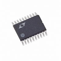
LTC1735CF Linear Technology, LTC1735CF Datasheet - Page 20

LTC1735CF
Manufacturer Part Number
LTC1735CF
Description
IC SW REG SYNC STEP-DWN 20-TSSOP
Manufacturer
Linear Technology
Type
Step-Down (Buck)r
Datasheet
1.LTC1735CSPBF.pdf
(32 pages)
Specifications of LTC1735CF
Internal Switch(s)
No
Synchronous Rectifier
Yes
Number Of Outputs
1
Voltage - Output
0.8 ~ 6 V
Current - Output
3A
Frequency - Switching
300kHz
Voltage - Input
4 ~ 30 V
Operating Temperature
0°C ~ 85°C
Mounting Type
Surface Mount
Package / Case
20-TSSOP
Lead Free Status / RoHS Status
Contains lead / RoHS non-compliant
Power - Output
-
Available stocks
Company
Part Number
Manufacturer
Quantity
Price
Company:
Part Number:
LTC1735CF
Manufacturer:
Linear Technology
Quantity:
135
Part Number:
LTC1735CFE
Manufacturer:
LINEAR/凌特
Quantity:
20 000
LTC1735
APPLICATIO S I FOR ATIO
FCB Pin Operation
When the FCB pin drops below its 0.8V threshold, continu-
ous mode operation is forced. In this case, the top and
bottom MOSFETs continue to be driven synchronously
regardless of the load on the main output. Burst Mode
operation is disabled and current reversal is allowed in the
inductor.
In addition to providing a logic input to force continuous
synchronous operation and external synchronization, the
FCB pin provides a means to regulate a flyback winding
output (refer to Figure 3a). During continuous mode,
current flows continuously in the transformer primary.
The secondary winding(s) draw current only when the
bottom, synchronous switch is on. When primary load
currents are low and/or the V
synchronous switch may not be on for a sufficient amount
of time to transfer power from the output capacitor to the
secondary load. Forced continuous operation will support
secondary windings provided there is sufficient synchro-
nous switch duty factor. Thus, the FCB input pin removes
the requirement that power must be drawn from the
inductor primary in order to extract power from the
auxiliary windings. With the loop in continuous mode, the
auxiliary outputs may nominally be loaded without regard
to the primary output load.
The secondary output voltage V
shown in Figure 3a by the turns ratio N of the transformer:
However, if the controller goes into Burst Mode operation
and halts switching due to a light primary load current,
then V
V
If V
continuous switching operation until V
its minimum.
In order to prevent erratic operation if no external connec-
tions are made to the FCB pin, the FCB pin has a 0.17 A
internal current source pulling the pin high. Remember to
20
SEC
V
SEC
SEC MIN
to the FCB pin sets a minimum voltage V
SEC
(
V
drops below this level, the FCB voltage forces
SEC
will droop. An external resistive divider from
)
(N + 1)V
. 0 8
V
U
1
OUT
R
R
U
4
3
IN
/V
SEC
OUT
W
is normally set as
SEC
ratio is low, the
is again above
SEC(MIN)
U
:
include this current when choosing resistor values R3
and R4.
The internal LTC1735 oscillator can be synchronized to an
external oscillator by applying and clocking the FCB pin
with a signal above 1.5V
external frequency, Burst Mode operation is disabled but
cycle skipping is allowed at low load currents since current
reversal is inhibited. The bottom gate will come on every
10 clock cycles to assure the bootstrap cap is kept re-
freshed. The rising edge of an external clock applied to the
FCB pin starts a new cycle. The FCB pin must not be driven
when the device is in shutdown (RUN/SS pin low).
The range of synchronization is from 0.9f
f
frequency than 1.3f
pensation and cause loop instability with high duty cycles
(duty cycle > 50%). If loop instability is observed while
synchronized, additional slope compensation can be ob-
tained by simply decreasing C
The following table summarizes the possible states avail-
able on the FCB pin:
Table 1
FCB Pin
DC Voltage: 0V to 0.7V
DC Voltage: 0.9V
Feedback Resistors
Ext Clock: (0V to V
Efficiency Considerations
The percent efficiency of a switching regulator is equal to
the output power divided by the input power times 100%.
It is often useful to analyze individual losses to determine
what is limiting the efficiency and which change would
produce the most improvement. Percent efficiency can be
expressed as:
where L1, L2, etc. are the individual losses as a percentage
of input power.
O
%Efficiency = 100% – (L1 + L2 + L3 + …)
set by C
(V
FCBSYNC
OSC
FCBSYNC
. Attempting to synchronize to a higher
> 1.5V)
O
)
can result in inadequate slope com-
P–P
Condition
Burst Disabled/Forced Continuous
Current Reversal Enabled
Burst Mode Operation,
No Current Reversal
Regulating a Secondary Winding
Burst Mode Operation Disabled
No Current Reversal
. When synchronized to an
OSC
.
O
to 1.3f
O
, with
1735fc


