LM3207TL-2.53/NOPB National Semiconductor, LM3207TL-2.53/NOPB Datasheet - Page 17
LM3207TL-2.53/NOPB
Manufacturer Part Number
LM3207TL-2.53/NOPB
Description
IC BUCK SYNC 2.53V .65A 9USMD
Manufacturer
National Semiconductor
Series
PowerWise®r
Type
Step-Down (Buck)r
Datasheet
1.LM3207TLNOPB.pdf
(24 pages)
Specifications of LM3207TL-2.53/NOPB
Internal Switch(s)
Yes
Synchronous Rectifier
Yes
Number Of Outputs
1
Voltage - Output
2.53V
Current - Output
650mA
Frequency - Switching
2MHz
Voltage - Input
2.7 ~ 5.5 V
Operating Temperature
-30°C ~ 85°C
Mounting Type
Surface Mount
Package / Case
9-MicroSMD
For Use With
LM3207TL-2.53EV - BOARD EVAL LM3207 WCDMA/CDMALM3207TLEV - BOARD EVALUATION LM3207TL
Lead Free Status / RoHS Status
Lead free / RoHS Compliant
Power - Output
-
Other names
LM3207TL-2.53TR


Operation Description
The LM3207 is a simple, step-down DC-DC converter with a
VREF LDO optimized for powering RF power amplifiers (PAs)
in mobile phones, portable communicators, and similar bat-
tery powered RF devices. The DC-DC converter is designed
to allow the RF PA to operate at maximum efficiency over a
wide range of power levels from a single Lithium-Ion battery
cell. The DC-DC is based on current-mode buck architecture,
with synchronous rectification for high efficiency. It is de-
signed for a maximum load capability of 650mA in PWM
mode.
Maximum load range may vary from this depending on input
voltage, output voltage and the inductor chosen.
The device has two pin-selectable operating modes required
for powering RF PAs in mobile phones and other sophisticat-
ed portable devices. Fixed-frequency PWM operation offers
regulated output at high efficiency while minimizing interfer-
ence with sensitive IF and data acquisition circuits. Shutdown
mode turns the device off and reduces battery consumption
to 0.01uA (typ).
Efficiency is typically around 95% for a 400mA load with
3.9V
grammable from 0.8V (typ) to 3.6V (typ) by adjusting the
Circuit Operation (DC-DC
Converter)
Referring to Figure 1 and Figure 2, the LM3207 operates as
follows. During the first part of each switching cycle, the con-
trol block in the LM3207 turns on the internal PFET (P-
channel MOSFET) switch. This allows current to flow from the
input through the inductor to the output filter capacitor and
load. The inductor limits the current to a ramp with a slope of
around (PV
During the second part of each cycle, the controller turns the
PFET switch off, blocking current flow from the input, and then
turns the NFET (N-channel MOSFET) synchronous rectifier
on. In response, the inductor’s magnetic field collapses, gen-
erating a voltage that forces current from ground through the
synchronous rectifier to the output filter capacitor and load.
As the stored energy is transferred back into the circuit and
depleted, the inductor current ramps down with a slope
around V
IN
, 3.4V
OUT
IN
OUT
- V
/ L. The output filter capacitor stores charge
OUT
. The output voltage is dynamically pro-
) / L, by storing energy in a magnetic field.
FIGURE 3. Typical Application Circuit
17
voltage on the control pin without the need for external feed-
back resistors. This ensures longer battery life by being able
to change the PA supply voltage dynamically depending on
its transmitting power.
Additional features include current overload protection, and
thermal overload shutdown.
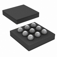
The LM3207 is constructed using a chip-scale 9-pin micro
SMD package. This package offers the smallest possible
size, for space-critical applications such as cell phones,
where board area is an important design consideration. Use
of a high switching frequency (2MHz) reduces the size of ex-
ternal components. As shown in Figure 1, only four external
power components are required for implementation. Use of a
micro SMD package requires special design considerations
for implementation. (See Micro SMD Package Assembly and
use in the Applications Information section.) The fine bump-
pitch requires careful board design and precision assembly
equipment. Use of this package is best suited for opaque-
case applications, where its edges are not subject to high-
intensity ambient red or infrared light. Also, the system
controller should set EN low during power-up and other low
supply voltage conditions. (See Shutdown Mode in the Device
Information section.)
when the inductor current is high, and releases it when low,
smoothing the voltage across the load.
The output voltage is regulated by modulating the PFET
switch on time to control the average current sent to the load.
The effect is identical to sending a duty-cycle modulated rect-
angular wave formed by the switch and synchronous rectifier
at SW to a low-pass filter formed by the inductor and output
filter capacitor. The output voltage is equal to the average
voltage at the SW pin.
PWM Operation
While in PWM (Pulse Width Modulation) mode, the output
voltage is regulated by switching at a constant frequency and
then modulating the energy per cycle to control power to the
load. Energy per cycle is set by modulating the PFET switch
on-time pulse width to control the peak inductor current. This
is done by comparing the signal from the current-sense am-
plifier with a slope compensated error signal from the voltage-
feedback error amplifier. At the beginning of each cycle, the
clock turns on the PFET switch, causing the inductor current
20165336
www.national.com
Related parts for LM3207TL-2.53/NOPB
Image
Part Number
Description
Manufacturer
Datasheet
Request
R

Part Number:
Description:
Manufacturer:
National Semiconductor
Datasheet:

Part Number:
Description:
IC CONV DC/DC 650MA ADJ 9USMD
Manufacturer:
National Semiconductor
Datasheet:
Part Number:
Description:
BOARD EVAL LM3207 WCDMA/CDMA
Manufacturer:
National Semiconductor
Datasheet:
Part Number:
Description:
LM3207 650mA Miniature, Adjustable, Step-Down DC-DC Converter for RF Power Amplifiers with Integrated Vref LDO; Package: MICRO SMD; No of Pins: 9; Qty per Container: 250; Container: Reel
Manufacturer:
National Semiconductor
Datasheet:
Part Number:
Description:
National Semiconductor [8-Bit D/A Converter]
Manufacturer:
National Semiconductor
Datasheet:
Part Number:
Description:
National Semiconductor [Media Coprocessor]
Manufacturer:
National Semiconductor
Datasheet:
Part Number:
Description:
Digitally Controlled Tone and Volume Circuit with Stereo Audio Power Amplifier, Microphone Preamp Stage and National 3D Sound
Manufacturer:
National Semiconductor
Datasheet:
Part Number:
Description:
Digitally Controlled Tone and Volume Circuit with Stereo Audio Power Amplifier, Microphone Preamp Stage and National 3D Sound
Manufacturer:
National Semiconductor
Datasheet:
Part Number:
Description:
AC97 Rev 2 Codec with Sample Rate Conversion and National 3D Sound
Manufacturer:
National Semiconductor
Part Number:
Description:
Manufacturer:
National Semiconductor
Datasheet:
Part Number:
Description:
Manufacturer:
National Semiconductor
Datasheet:
Part Number:
Description:
General Purpose, Low Voltage, Low Power, Rail-to-Rail Output Operational Amplifiers
Manufacturer:
National Semiconductor
Datasheet:
Part Number:
Description:
8-bit 20 MSPS flash A/D converter.
Manufacturer:
National Semiconductor
Datasheet:
Part Number:
Description:
Low Noise Quad Operational Amplifier
Manufacturer:
National Semiconductor
Datasheet: