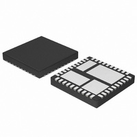
NCP3102BMNTXG ON Semiconductor, NCP3102BMNTXG Datasheet - Page 8

NCP3102BMNTXG
Manufacturer Part Number
NCP3102BMNTXG
Description
IC CONV SYNC BUCK 10A 40QFN
Manufacturer
ON Semiconductor
Type
Step-Down (Buck)r
Datasheet
1.NCP3102BMNTXG.pdf
(18 pages)
Specifications of NCP3102BMNTXG
Internal Switch(s)
Yes
Synchronous Rectifier
Yes
Number Of Outputs
1
Voltage - Output
Adj to 0.8V
Current - Output
10A
Frequency - Switching
275kHz
Voltage - Input
4.5 ~ 13.2 V
Operating Temperature
-40°C ~ 125°C
Mounting Type
Surface Mount
Package / Case
40-TQFN Exposed Pad
Power - Output
3W
Lead Free Status / RoHS Status
Lead free / RoHS Compliant
Other names
NCP3102BMNTXGOSTR
required, to realize the full benefit of the onboard drivers.
The capacitors between V
and PHASE must be placed as close as possible to the
device. A ground plane should be placed on the closest layer
for return currents to GND in order to reduce loop area and
inductance in the gate drive circuit.
Input Capacitor Selection
produced during the on time of the upper MOSFET, so it
must have a low ESR to minimize the losses. The RMS value
of this ripple is:
Where D is the duty cycle, Iin
and I
maximum value with D = 0.5. Losses in the input capacitors
can be calculated with the following equation:
Where P
ESR
capacitance. Due to large di/dt through the input capacitors,
electrolytic or ceramics should be used. If a tantalum
capacitor has to be used, surge protection is needed.
Otherwise, capacitor failure could occur.
Calculating Input Startup current
equation can be used:
PWM
OUT
Careful selection and layout of external components is
The input capacitor has to sustain the ripple current
To calculate the input startup current, the following
CIN
OUT
Iin
P
I
inrush
CIN
CIN
is the effective series resistance of the input
FAULT
UVLO
RMS
is the load current. The equation reaches its
+ ESR
is the power loss in the input capacitors and
+
+ I
Figure 15. Block Diagram
APPLICATION SECTION
C
OUT
OUT
CIN
t
SS
UVLO
FAULT
D
V
-
-
CC
+
+
Iin
OUT
( 1 * D )
RMS
RMS
and GND and between BST
2 V
2 V
2
is the input RMS current,
PHASE
BST
TG
V
BG
GND
(eq. 2)
(eq. 3)
(eq. 4)
http://onsemi.com
CC
NCP3102
8
where I
total output capacitance, V
and t
current during maximum load, then the input fuse should be
rated accordingly, if one is used.
Calculating Soft-Start Time
can be used.
Where C
capacitor.
C
I
DV is the comp voltage from zero to until it reaches
regulation.
rising to when output voltage becomes valid.
reaches regulation; DV is the difference between the comp
voltage reaching regulation and 1.1 V.
Output Capacitor Selection
determines the behavior of the buck converter. In most high
power density applications the capacitor size is most
important. Ceramic capacitor is necessary to reduce the high
frequency ripple voltage at the input of converter. This
capacitor should be located near the device as possible.
Added electrolytic capacitor improved response of relative
slow load change.
planned transient deviation requirements. Usually a
combination of two types of capacitors is recommended to
meet the requirements. First, a ceramic output capacitor is
needed for bypassing high frequency noise. Second, an
electrolytic output capacitor is needed to achieve good
transient response.
microseconds the bulk capacitance supplies current to the
load. The controller immediately recognizes the load
SS
V
P
If the inrush current is higher than the steady state input
To calculate the soft-start time, the following equation
The above calculation includes the delay from comp
To calculate the time of output voltage rising to when it
Selection of the right value of input and output capacitors
The required output capacitor will be determined by
In fact, during load transient, for the first few
comp
V
is the additional capacitor that forms the second pole.
is the soft-start current
out
SS
inrush
t
is the soft-start interval.
SS
C
+
is the compensation as well as the soft-start
is the input current during startup, C
C
p
) C
Figure 16. Soft-Start
I
SS
c
DV
* DV
OUT
1.1 V
is the desired output voltage,
OUT
(eq. 5)
is the


