EL7566DREZ Intersil, EL7566DREZ Datasheet
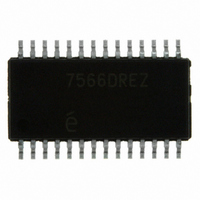
IC REG 6A DC-DC STEP DN 28HTSSOP

EL7566DREZ

Manufacturer Part Number
EL7566DREZ
Description
IC REG 6A DC-DC STEP DN 28HTSSOP
Manufacturer
Intersil
Type
Step-Down (Buck)r
Datasheet

Specifications of EL7566DREZ

Internal Switch(s)
Yes
Synchronous Rectifier
Yes
Number Of Outputs
1
Voltage - Output
0.8 ~ 6 V
Current - Output
6A
Frequency - Switching
370kHz
Voltage - Input
3 ~ 6 V
Operating Temperature
0°C ~ 85°C
Mounting Type
Surface Mount
Package / Case
28-TSSOP Exposed Pad, 28-eTSSOP, 28-HTSSOP
Lead Free Status / RoHS Status
Lead free / RoHS Compliant
Power - Output
-

Available stocks

Company
Part Number
Manufacturer
Quantity
Price
Part Number:
EL7566DREZ
Manufacturer:
INTERSIL
Quantity:
114
Part Number:
EL7566DREZ
Manufacturer:
EL
Quantity:
20 000
Part Number:
EL7566DREZ-T7
Manufacturer:
Intersil
Quantity:
4 050
Monolithic 6A DC/DC Step-Down
Regulator
The EL7566 is a full-feature synchronous step-down regulator
capable of up to 6A and 96% efficiency. The device operates
from 3V to 6V input supply (V
FETs, the device can operate at up to 100% duty ratio,
allowing for an output voltage range of 0.8V to nearly V
adjustable switching frequency up to 1MHz enables the use of
small components, thereby reducing board area consumption
to under 0.72sq-in on one side of a PCB. The EL7566
operates in constant frequency PWM mode, making external
synchronization possible. A soft-start feature is integrated in
the EL7566 to limit in-rush currents and allow for a smooth
voltage ramp from zero to regulation. Other start-up features
are integrated to add flexibility for synchronizing many
supplies in multiple configurations. The EL7566 also offers a
voltage margining capability that shifts the output voltage ±5%
for validation of system card performance and reliability during
manufacturing tests. A junction temperature indicator
conveniently monitors the silicon die temperature, saving time
in thermal characterization.
An easy-to-use simulation tool is available for
can be used to modify design parameters such as switching
frequency, voltage ripple, ambient temperature, as well as
view schematics waveforms, efficiency graphs, and
complete BOM with Gerber layout.
®
IN
1
). With internal CMOS power
Data Sheet
download
IN
1-888-INTERSIL or 1-888-468-3774
. An
and
CAUTION: These devices are sensitive to electrostatic discharge; follow proper IC Handling Procedures.
Features
• Integrated MOSFETs
• 6A continuous output current
• Up to 96% efficiency
• Multiple supply start-up tracking
• Built-in ±5% voltage margining
• 3V to 6V input voltage
• 0.72 in
• Adjustable switching frequency to 1MHz
• Oscillator synchronization possible
• 100% duty ratio
• Junction temperature indicator
• Over-temperature protection
• Internal soft-start
• Variable output voltage down to 0.8V
• Power-good indicator
• 28 Ld HTSSOP package
• Pb-free plus anneal available (RoHS compliant)
Applications
• Point-of-regulation power supplies
• FPGA Core and I/O supplies
• DSP, CPU Core, and IO supplies
• Logic/Bus supplies
• Portable equipment
Related Documentation
• Technical Brief 415 - Using the EL7566 Demo Board
• Easy-to-use applications software simulation tool available
at
www.intersil.com/dc-dc
All other trademarks mentioned are the property of their respective owners.
2
|
footprint with components on one side of PCB
May 8, 2006
Intersil (and design) is a registered trademark of Intersil Americas Inc.
Copyright © Intersil Americas Inc. 2004, 2006. All Rights Reserved.
EL7566
FN7102.7

Related parts for EL7566DREZ

EL7566DREZ Summary of contents

Page 1

... CAUTION: These devices are sensitive to electrostatic discharge; follow proper IC Handling Procedures. | 1-888-INTERSIL or 1-888-468-3774 Intersil (and design registered trademark of Intersil Americas Inc. Copyright © Intersil Americas Inc. 2004, 2006. All Rights Reserved. All other trademarks mentioned are the property of their respective owners. ...

Page 2

... EL7566DRE-T7 7566DRE EL7566DRE-T13 7566DRE EL7566DREZ (Note) 7566DREZ EL7566DREZ-T7 (Note) 7566DREZ EL7566DREZ-T13 (Note) 7566DREZ EL7566AIREZ (Note) 7566AIREZ EL7566AIREZ-T7 (Note) 7566AIREZ EL7566AIREZ-T13 (Note) 7566AIREZ NOTE: Intersil Pb-free plus anneal products employ special Pb-free material sets; molding compounds/die attach materials and 100% matte tin plate termination finish, which are RoHS compliant and compatible with both SnPb and Pb-free soldering operations ...

Page 3

Absolute Maximum Ratings ( SGND -0.3V to +6.5V IN ...

Page 4

DC Electrical Specifications V PARAMETER DESCRIPTION V EN Input High Threshold EN_HI V EN Input Low Threshold EN_LO I Enable Pull-up Current EN TM, S Input High Level EL_HI TM, S Input Low Level EL_LO Pin Descriptions PIN NUMBER PIN ...

Page 5

Block Diagram V TJ JUNCTION TEMPERATURE V DD 2.2nF EN STP POWER TRACKING STN EA COMP SGND 5 EL7566 TM 0.047µF 390pF SEL V C REF OSC VOLTAGE OSCILLATOR REFERENCE PWM CONTROLLER DRIVERS CURRENT SENSE V ...

Page 6

Typical Performance Curves 5V 2.5V 6A 500kHz 2.7µ 100 V =3. =0. =1V ...

Page 7

Typical Performance Curves 5V 2.5V 6A 500kHz 2.7µ 526 524 522 V =5V IN 520 518 516 514 512 V =3.3V 510 ...

Page 8

Waveforms 5V 2.5V 6A 500kHz 2.7µ 0.5ms/DIV FIGURE 12. START-UP 50µs/DIV FIGURE 14. SHUT-DOWN 1ms/DIV FIGURE 16. VOLTAGE MARGINING 8 EL7566 = ...

Page 9

Waveforms 5V 2.5V 6A 500kHz 2.7µ 5ms/DIV FIGURE 18. ADJUSTABLE START-UP Detailed Description The EL7566 capable buck regulator operating ...

Page 10

It also allows 100% turn-on of the upper PMOS switch, achieving V close The maximum achievable × – DSON1 O Where R ...

Page 11

The V pin reports a voltage proportional to the junction TJ temperature. Equation 3 illustrates the relationship and can be used to accurately evaluate thermal design points. 1.2 V – ------------------------ = + J 0.00384 Full Start-Up ...

Page 12

INDUCTOR The NMOS positive current limit is set at about 8A. For optimal operation, the peak-to-peak inductor current ripple ΔI should be less than 1A. The following equation gives the L inductance value × – ...

Page 13

For convenience, Table 3 lists the compensation values for frequently used output voltages. TABLE 3. COMPENSATION VALUES V (V) R (kΩ 3.3 13.7 2.5 10.5 1.8 7.68 1.5 6.49 1.2 5.23 1 4.42 0.8 3.57 Thermal Management The ...

Page 14

... Accordingly, the reader is cautioned to verify that data sheets are current before placing orders. Information furnished by Intersil is believed to be accurate and reliable. However, no responsibility is assumed by Intersil or its subsidiaries for its use; nor for any infringements of patents or other rights of third parties which may result from its use ...

Related keywords