LM2592HVS-5.0/NOPB National Semiconductor, LM2592HVS-5.0/NOPB Datasheet
LM2592HVS-5.0/NOPB
Specifications of LM2592HVS-5.0/NOPB
*LM2592HVS-5.0/NOPB
LM2592HVS-5.0


Related parts for LM2592HVS-5.0/NOPB


LM2592HVS-5.0/NOPB Summary of contents
Page 1
... Output Voltage Versions) SIMPLE SWITCHER ® and Switchers Made Simple ® are registered trademarks of National Semiconductor Corporation. © 2001 National Semiconductor Corporation Power Converter 150 kHz 2A ® current limit for the output switch and an over temperature shutdown for complete protection under fault conditions. ...
Page 2
... Absolute Maximum Ratings If Military/Aerospace specified devices are required, please contact the National Semiconductor Sales Office/ Distributors for availability and specifications. Maximum Supply Voltage ( ON/OFF Pin Voltage Feedback Pin Voltage Output Voltage to Ground (Steady State) Power Dissipation Storage Temperature Range ESD Susceptibility LM2592HV-3 ...
Page 3
All Output Voltage Versions Electrical Characteristics Specifications with standard type face are for T ture Range. Unless otherwise specified, V Symbol Parameter DEVICE PARAMETERS I Feedback Bias Current b f Oscillator Frequency O V Saturation Voltage SAT DC Max Duty ...
Page 4
... Note 13: Junction to ambient thermal resistance with the TO-263 package tab soldered to a single sided printed circuit board with 2.5 in Note 14: Junction to ambient thermal resistance with the TO-263 package tab soldered to a double sided printed circuit board with 3 in the LM2592HVS side of the board, and approximately 16 in model in Switchers Made Simple available at http://power.national.com. ...
Page 5
Typical Performance Characteristics Normalized Output Voltage 10129402 Switch Saturation Voltage 10129405 Operating Quiescent Current 10129408 (Circuit of Figure 1 ) Line Regulation 10129403 Switch Current Limit 10129406 Shutdown Quiescent Current 10129409 5 Efficiency 10129404 Dropout Voltage 10129407 Minimum Operating Supply ...
Page 6
Typical Performance Characteristics Feedback Pin Bias Current 10129411 ON/OFF Pin Current (Sinking) 10129480 www.national.com (Circuit of Figure 1 ) (Continued) Switching Frequency 10129413 Internal Gain-Phase Characteristics 10129478 6 ON/OFF Threshold Voltage 10129479 ...
Page 7
... Load Transient Response for Discontinuous Mode V = 20V ESR = µH, C Horizontal Time Base: 200 µs/div. 10129421 A: Output Voltage, 100 mV/div. (AC) B: 500 Load Pulse 10129481 Order Number LM2592HVS-3.3, LM2592HVS-5.0, See NS Package Number TS5B 7 = 20V 5V 500 mA OUT LOAD = 330 µF, C ESR = 45 m OUT ...
Page 8
Test Circuit and Layout Guidelines Component Values shown are for V = 15V 5V 2A. OUT LOAD C — 470 µF, 50V, Aluminum Electrolytic Nichicon “PM Series” — 220 µF, 25V Aluminum Electrolytic, ...
Page 9
Block Diagram PIN FUNCTIONS +V (Pin 1) — This is the positive input supply for the IC IN switching regulator. A suitable input bypass capacitor must be present at this pin to minimize voltage transients and to supply the switching ...
Page 10
INDUCTOR VALUE SELECTION GUIDES (For Continuous Mode Operation) www.national.com FIGURE 2. LM2592HV-3.3 FIGURE 3. LM2592HV-5.0 10 10129465 10129466 ...
Page 11
INDUCTOR VALUE SELECTION GUIDES (For Continuous Mode Operation) (Continued) FIGURE 4. LM2592HV-ADJ FIGURE 5. Current Ripple Ratio 11 10129467 10129468 www.national.com ...
Page 12
INDUCTOR VALUE SELECTION GUIDES Coilcraft Inc. Coilcraft Inc., Europe Pulse Engineering Inc. Pulse Engineering Inc., Europe Renco Electronics Inc. Schott Corp. Cooper Electronic Tech. (Coiltronics) FIGURE 6. Contact Information for Suggested Inductor Manufacturers www.national.com (For Continuous Mode Operation) (Continued) Phone ...
Page 13
Application Information INDUCTOR SELECTION PROCEDURE Application Note AN-1197 titled ’Selecting Inductors for Buck Converters’ provides detailed information on this topic. For a quick-start the designer may refer to the nomographs pro- vided in Figure 2 to Figure ...
Page 14
Application Information Therefore, looking at Figure 2 we quick-select a 47µH/2A inductor (designed for 150 kHz operation) for this applica- tion should confirm that it is rated to handle 200 µJ (see Figure the procedure ...
Page 15
Application Information UNDERVOLTAGE LOCKOUT Some applications require the regulator to remain off until the input voltage reaches a predetermined voltage. An und- ervoltage lockout feature applied to a buck regulator is shown in Figure 8 , while Figure 9 and ...
Page 16
Application Information sion. Since this regulator topology can produce an output voltage that is either greater than or less than the input voltage, the maximum output current greatly depends on both the input and output voltage. To determine how much ...
Page 17
... PC board with large copper areas and/or airflow are recommended. The curves shown in Figure 14 show the LM2592HVS (TO-263 package) junction temperature rise above ambient temperature with a 2A load for various input and output voltages ...
Page 18
Application Information PC board to simulate the junction temperature under actual operating conditions. This curve can be used for a quick check for the approximate junction temperature for various conditions, but be aware that there are many factors that can ...
Page 19
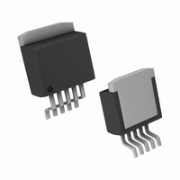
Physical Dimensions inches (millimeters) unless otherwise noted Order Number LM2592HVT-3.3, LM2592HVT-5.0 5-Lead TO-220 Bent and Staggered Package or LM2592HVT-ADJ NS Package Number T05D 19 www.national.com ...
Page 20
... Physical Dimensions Order Number LM2592HVS-3.3, LM2592HVS-5.0 or LM2592HVS-ADJ LIFE SUPPORT POLICY NATIONAL’S PRODUCTS ARE NOT AUTHORIZED FOR USE AS CRITICAL COMPONENTS IN LIFE SUPPORT DEVICES OR SYSTEMS WITHOUT THE EXPRESS WRITTEN APPROVAL OF THE PRESIDENT AND GENERAL COUNSEL OF NATIONAL SEMICONDUCTOR CORPORATION. As used herein: 1. Life support devices or systems are devices or ...