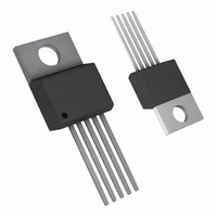
LM2577T-ADJ/NOPB National Semiconductor, LM2577T-ADJ/NOPB Datasheet - Page 17

LM2577T-ADJ/NOPB
Manufacturer Part Number
LM2577T-ADJ/NOPB
Description
IC REG SIMPLE SWITCHER TO-220-5
Manufacturer
National Semiconductor
Series
SIMPLE SWITCHER®r
Type
Step-Up (Boost), Flyback, Forward Converterr
Specifications of LM2577T-ADJ/NOPB
Internal Switch(s)
Yes
Synchronous Rectifier
No
Number Of Outputs
1
Voltage - Output
11.4 ~ 12.6 V
Current - Output
3A
Frequency - Switching
52kHz
Voltage - Input
3.5 ~ 40 V
Operating Temperature
-40°C ~ 125°C
Mounting Type
Through Hole
Package / Case
TO-220-5 (Straight Leads)
Current, Input Bias
100 nA
Current, Output
3 A
Current, Supply
25 mA
Frequency, Oscillator
52 kHz
Package Type
TO-220
Regulation, Line
20 mV
Regulation, Load
20 mV
Regulator Type
Boost (Step-Up)
Resistance, Thermal, Junction To Case
2 °C/W
Temperature, Operating, Range
-40 to +125 °C
Transconductance
3700
Voltage, Gain
800 V/V
Voltage, Input
3.5 to 40 V
Dc To Dc Converter Type
Step Up
Pin Count
5 +Tab
Input Voltage
40V
Output Voltage
11.6 to 12.4V
Switching Freq
48 TO 56KHz
Output Current
3A
Efficiency
80%
Output Type
Adjustable
Switching Regulator
Yes
Load Regulation
50mV
Line Regulation
50mV
Mounting
Through Hole
Input Voltage (min)
3.5V
Operating Temperature Classification
Automotive
For Use With
551011367-061 - BOARD WEBENCH LM2577,LM2585/87
Lead Free Status / RoHS Status
Lead free / RoHS Compliant
Power - Output
-
Lead Free Status / Rohs Status
RoHS Compliant part
Electrostatic Device
Other names
*LM2577T-ADJ
*LM2577T-ADJ/NOPB
LM2577T-ADJ
*LM2577T-ADJ/NOPB
LM2577T-ADJ
Available stocks
Company
Part Number
Manufacturer
Quantity
Price
Company:
Part Number:
LM2577T-ADJ/NOPB
Manufacturer:
TOSHIBA
Quantity:
7 600
Application Hints
Note: These charts assume that the inductor ripple current inductor is approximately 20% to 30% of the average inductor current (when the regulator is under
full load). Greater ripple current causes higher peak switch currents and greater output ripple voltage; lower ripple current is achieved with larger-value
inductors. The factor of 20 to 30% is chosen as a convenient balance between the two extremes.
C. Select an inductor from the table of Figure 10 which
cross-references the inductor codes to the part numbers
of three different manufacturers. Complete specifications
for these inductors are available from the respective
manufacturers. The inductors listed in this table have the
following characteristics:
AIE: ferrite, pot-core inductors; Benefits of this type are
low electro-magnetic interference (EMI), small physical
size, and very low power dissipation (core loss). Be
careful not to operate these inductors too far beyond their
maximum ratings for E • T and peak current, as this will
saturate the core.
Pulse: powdered iron, toroid core inductors; Benefits are
low EMI and ability to withstand E • T and peak current
above rated value better than ferrite cores.
Renco: ferrite, bobbin-core inductors; Benefits are low
cost and best ability to withstand E • T and peak current
above rated value. Be aware that these inductors gener-
ate more EMI than the other types, and this may interfere
with signals sensitive to noise.
FIGURE 9. LM1577-ADJ/LM2577-ADJ Inductor Selection Graph
(Continued)
17
01146812
www.national.com


