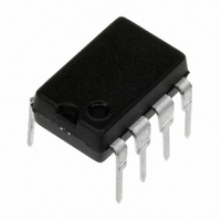
LM2597HVN-ADJ/NOPB National Semiconductor, LM2597HVN-ADJ/NOPB Datasheet - Page 29

LM2597HVN-ADJ/NOPB
Manufacturer Part Number
LM2597HVN-ADJ/NOPB
Description
IC REG SIMPLE SWITCHER 8-DIP
Manufacturer
National Semiconductor
Series
SIMPLE SWITCHER®r
Type
Step-Down (Buck)r
Datasheet
1.LM2597M-3.3NOPB.pdf
(34 pages)
Specifications of LM2597HVN-ADJ/NOPB
Internal Switch(s)
Yes
Synchronous Rectifier
No
Number Of Outputs
1
Voltage - Output
1.2 ~ 37 V
Current - Output
500mA
Frequency - Switching
150kHz
Voltage - Input
4.5 ~ 60 V
Operating Temperature
-40°C ~ 125°C
Mounting Type
Through Hole
Package / Case
8-DIP (0.300", 7.62mm)
Supply Voltage Range
4.5V To 60V
Driver Case Style
NSOIC
No. Of Pins
8
Output Voltage Min
1.23V
Voltage Regulator Type
Buck Switching
Rohs Compliant
Yes
Input Voltage Primary Max
60V
No. Of Outputs
1
Operating Temperature Range
-40°C To +125°C
Output Current
500mA
Lead Free Status / RoHS Status
Lead free / RoHS Compliant
Power - Output
-
Other names
*LM2597HVN-ADJ
*LM2597HVN-ADJ/NOPB
LM2597HVN-ADJ
*LM2597HVN-ADJ/NOPB
LM2597HVN-ADJ
Application Information
lNVERTING REGULATOR
The circuit in Figure 29 converts a positive input voltage to a
negative output voltage with a common ground. The circuit
operates by bootstrapping the regulators ground pin to the
negative output voltage, then grounding the feedback pin,
the regulator senses the inverted output voltage and regu-
lates it.
This example uses the LM2597-5 to generate a −5V output,
but other output voltages are possible by selecting other
output voltage versions, including the adjustable version.
Since this regulator topology can produce an output voltage
that is either greater than or less than the input voltage, the
maximum output current greatly depends on both the input
and output voltage. The curve shown in Figure 30 provides a
guide as to the amount of output load current possible for the
different input and output voltage conditions.
FIGURE 28. Typical Circuit Using Shutdown /Soft-start and Error Flag Features
FIGURE 29. Inverting −5V Regulator With Shutdown and Soft-start
(Continued)
29
The maximum voltage appearing across the regulator is the
absolute sum of the input and output voltage, and this must
be limited to a maximum of 40V. In this example, when
converting +20V to −5V, the regulator would see 25V be-
tween the input pin and ground pin. The LM2597 has a
maximum input voltage rating of 40V (60V for the
LM2597HV).
DS012440-48
www.national.com
DS012440-47


