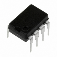
LM3578AN/NOPB National Semiconductor, LM3578AN/NOPB Datasheet - Page 6

LM3578AN/NOPB
Manufacturer Part Number
LM3578AN/NOPB
Description
IC REGULATOR SWITCHING 8-DIP
Manufacturer
National Semiconductor
Type
Step-Down (Buck), Step-Up (Boost), Inverting, Flybackr
Specifications of LM3578AN/NOPB
Internal Switch(s)
Yes
Synchronous Rectifier
No
Number Of Outputs
1
Current - Output
750mA
Frequency - Switching
20kHz
Voltage - Input
2 ~ 40 V
Operating Temperature
0°C ~ 70°C
Mounting Type
Through Hole
Package / Case
8-DIP (0.300", 7.62mm)
Current, Input Bias
4 μA
Current, Output
750 mA
Current, Supply
14 mA
Frequency, Oscillator
20 kHz
Package Type
DIP-8
Regulation, Line
0.003 %/V
Regulator Type
Boost, Buck, DC-DC, Switching
Temperature, Operating, Range
0 to +125 °C
Voltage, Input
2 to 40 V
Lead Free Status / RoHS Status
Lead free / RoHS Compliant
Voltage - Output
-
Power - Output
-
Lead Free Status / Rohs Status
RoHS Compliant part
Electrostatic Device
Other names
*LM3578AN
*LM3578AN/NOPB
LM3578AN
LM3578N
*LM3578AN/NOPB
LM3578AN
LM3578N
www.national.com
Typical Performance Characteristics
Test Circuit*
Parameter tests can be made using the test circuit shown.
Select the desired V
adjustable power supplies. A digital volt meter with an input
resistance greater than 100 MΩ should be used to measure
the following:
Input Reference Voltage to Ground; S1 in either position.
Level Shift Accuracy (%) = (T
= 1 mA
Input Current (mA) = (1V − T
0 mA.
Oscillator parameters can be measured at T
quency counter or an oscilloscope.
Current Limit Sense Voltage
in
vs Supply Voltage
, collector voltage and duty cycle with
Supply Current
P3
p3
(V)/1V) x 100%; S1 at I
(V))/1 MΩ: S1 at I
p4
00871140
00871142
using a fre-
1
= I
1
= I
2
=
2
6
(Continued)
The Current Limit Sense Voltage is measured by connecting
an adjustable 0-to-1V floating power supply in series with the
current limit terminal and referring it to either the ground or
the V
point T
until the LM2578A’s duty cycle just reaches 0%. This voltage
is the Current Limit Sense Voltage.
The Supply Current should be measured with the duty cycle
at 0% and S1 in the I
*LM2578A specifications are measured using automated
test equipment. This circuit is provided for the customer’s
convenience when checking parameters. Due to possible
variations in testing conditions, the measured values from
these testing procedures may not match those of the factory.
in
P5
terminal. Set the duty cycle to 90% and monitor test
while adjusting the floating power supply voltage
Emitter Output Below Ground
Collector Current with
Supply Current
1
= I
2
= 0 mA position.
00871141
00871143


