LM3488MM/NOPB National Semiconductor, LM3488MM/NOPB Datasheet - Page 17
LM3488MM/NOPB
Manufacturer Part Number
LM3488MM/NOPB
Description
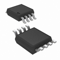
IC CTRLR SWITCH REG N-CH 8-MSOP
Manufacturer
National Semiconductor
Type
Step-Up (Boost), Flyback, Sepicr
Datasheet
1.LM3488MMNOPB.pdf
(24 pages)
Specifications of LM3488MM/NOPB
Internal Switch(s)
No
Synchronous Rectifier
No
Number Of Outputs
1
Voltage - Output
Adj to 1.26V
Current - Output
1A
Frequency - Switching
100kHz ~ 1MHz
Voltage - Input
2.97 ~ 40 V
Operating Temperature
-40°C ~ 125°C
Mounting Type
Surface Mount
Package / Case
8-MSOP, Micro8™, 8-uMAX, 8-uSOP,
Lead Free Status / RoHS Status
Lead free / RoHS Compliant
Power - Output
-
Other names
LM3488MM
LM3488MM
LM3488MMTR
LM3488MM
LM3488MMTR
Available stocks
Company
Part Number
Manufacturer
Quantity
Price
Company:

Part Number:
LM3488MM/NOPB
Manufacturer:
TI
Quantity:
15 540


SETTING THE CURRENT LIMIT
The maximum amount of current that can be delivered to the
load is set by the sense resistor, R
when the voltage that is generated across the sense resistor
equals the current sense threshold voltage, V
this threshold is reached, the switch will be turned off until the
next cycle. Limits for V
characteristics section. V
ue of the internal control signal V
however, is not a constant value and changes over the course
of a period as a result of the internal compensation ramp (See
Figure 3). Therefore the current limit threshold will also
change. The actual current limit threshold is a function of the
sense voltage (V
Where ISW
equation below. As duty cycle increases, the control voltage
is reduced as V
varies with duty cycle, the following equation should be used
to select R
The numerator of the above equation is V
calculated as:
To avoid false triggering, the current limit value should have
some margin above the maximum operating value, typically
120%. Values for both V
characteristic table. However, calculating with the limits of
these two specs could result in an unrealistically wide current
limit or R
ommended, using the V
R
influence on control loop stability. Therefore, once the current
limit threshold is set, loop stability must be verified. To verify
stability, use the following equation:
If the selected R
compensation must be added to ensure stability, as described
in the section below.
CURRENT LIMIT WITH EXTERNAL SLOPE
COMPENSATION
R
quired. It is not necessary in most designs and R
no larger than necessary. Select R
ing equation:
SEN
SL
is used to add additional slope compensation when re-
is part of the current mode control loop and has some
R
SEN
SEN
SEN
LIMIT
x ISW
range. Therefore, the following equation is rec-
and set the desired current limit threshold:
SEN
is the peak switch current limit, defined by the
SENSE
SL
LIMIT
ramps up. Since current limit threshold
is greater than this value, additional slope
) and the internal compensation ramp:
= VCS
SENSE
SL
SENSE
SENSE
ratio value given in the EC table:
MAX
are specified in the electrical
represents the maximum val-
and V
= V
SL
SEN
CS
according to the follow-
SENSE
SL
. This control signal,
. Current limit occurs
are specified in the
CS
- (D x V
, and ISW
SENSE
SL
should be
SL
. When
)
LIMIT
is
17
Where R
R
slope to stabilize the loop, which will also have an effect on
the current limit threshold. Therefore, the current limit thresh-
old must be re-verified, as illustrated in the equations below :
Where ΔV
and calculated as:
This changes the equation for current limit (or R
The R
in order to achieve both the desired current limit and stable
operation. In some designs R
on the ISEN pin.
If the inductor is selected such that ripple current is the rec-
ommended 30% value, and the current limit threshold is 120%
of the maximum peak, a simpler method can be used to de-
termine R
bility without RSL, provided that the above 2 conditions are
met:
POWER DIODE SELECTION
Observation of the boost converter circuit shows that the av-
erage current through the diode is the average load current,
and the peak current through the diode is the peak current
through the inductor. The diode should be rated to handle
more than its peak current. The peak diode current can be
calculated using the formula:
In the above equation, I
been defined in
The peak reverse voltage for boost converter is equal to the
regulator output voltage. The diode must be capable of han-
dling this voltage. To improve efficiency, a low forward drop
schottky diode is recommended.
POWER MOSFET SELECTION
The drive pin of LM3488 must be connected to the gate of an
external MOSFET. In a boost topology, the drain of the ex-
ternal N-Channel MOSFET is connected to the inductor and
the source is connected to the ground. The drive pin (DR)
voltage depends on the input voltage (see typical perfor-
mance characteristics). In most applications, a logic level
MOSFET can be used. For very low input voltages, a sub-
logic level MOSFET should be used.
The selected MOSFET directly controls the efficiency. The
critical parameters for selection of a MOSFET are:
1.
SL
installed, the control signal includes additional external
Minimum threshold voltage, V
SEN
SEN
and R
SEN
SL
is the selected value based on current limit. With
is the additional slope compensation generated
V
. The equation below will provide optimum sta-
CS
SL
Figure 11
I
= V
values may have to be calculated iteratively
D(Peak)
ΔV
SENSE
SL
OUT
= I
= 40 µA x R
– (D x (V
OUT
is the output current and ΔI
SL
/ (1−D) + ΔI
can also help to filter noise
TH
SL
(MIN)
SL
+ ΔV
L
SL
))
SEN
www.national.com
) to:
L
has
Related parts for LM3488MM/NOPB
Image
Part Number
Description
Manufacturer
Datasheet
Request
R

Part Number:
Description:
Manufacturer:
National Semiconductor
Datasheet:

Part Number:
Description:
IC, N-CH CONTROLLER, MSOP-8
Manufacturer:
National Semiconductor
Datasheet:
Part Number:
Description:
Manufacturer:
National Semiconductor
Datasheet:
Part Number:
Description:
National Semiconductor [8-Bit D/A Converter]
Manufacturer:
National Semiconductor
Datasheet:
Part Number:
Description:
National Semiconductor [Media Coprocessor]
Manufacturer:
National Semiconductor
Datasheet:
Part Number:
Description:
Digitally Controlled Tone and Volume Circuit with Stereo Audio Power Amplifier, Microphone Preamp Stage and National 3D Sound
Manufacturer:
National Semiconductor
Datasheet:
Part Number:
Description:
Digitally Controlled Tone and Volume Circuit with Stereo Audio Power Amplifier, Microphone Preamp Stage and National 3D Sound
Manufacturer:
National Semiconductor
Datasheet:
Part Number:
Description:
AC97 Rev 2 Codec with Sample Rate Conversion and National 3D Sound
Manufacturer:
National Semiconductor
Part Number:
Description:
Manufacturer:
National Semiconductor
Datasheet:
Part Number:
Description:
Manufacturer:
National Semiconductor
Datasheet:
Part Number:
Description:
General Purpose, Low Voltage, Low Power, Rail-to-Rail Output Operational Amplifiers
Manufacturer:
National Semiconductor
Datasheet:
Part Number:
Description:
8-bit 20 MSPS flash A/D converter.
Manufacturer:
National Semiconductor
Datasheet:
Part Number:
Description:
Low Noise Quad Operational Amplifier
Manufacturer:
National Semiconductor
Datasheet:
Part Number:
Description:
Quad Differential Line Receivers
Manufacturer:
National Semiconductor
Datasheet: