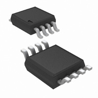
LM3478MM/NOPB National Semiconductor, LM3478MM/NOPB Datasheet - Page 14

LM3478MM/NOPB
Manufacturer Part Number
LM3478MM/NOPB
Description
IC CTRLR SW REG N-CH 8MSOP
Manufacturer
National Semiconductor
Type
Step-Up (Boost), Flyback, Sepicr
Datasheet
1.LM3478MMNOPB.pdf
(24 pages)
Specifications of LM3478MM/NOPB
Internal Switch(s)
No
Synchronous Rectifier
No
Number Of Outputs
1
Voltage - Output
Adjustable
Current - Output
1A
Frequency - Switching
100kHz ~ 1MHz
Voltage - Input
2.97 ~ 40 V
Operating Temperature
-40°C ~ 125°C
Mounting Type
Surface Mount
Package / Case
8-MSOP, Micro8™, 8-uMAX, 8-uSOP,
For Use With
LM3478EVAL - BOARD EVALUATION LM3478
Lead Free Status / RoHS Status
Lead free / RoHS Compliant
Power - Output
-
Other names
LM3478MM
LM3478MMTR
LM3478MMTR
Available stocks
Company
Part Number
Manufacturer
Quantity
Price
Part Number:
LM3478MM/NOPB
Manufacturer:
TI/德州仪器
Quantity:
20 000
www.national.com
POWER INDUCTOR SELECTION
The inductor is one of the two energy storage elements in a
boost converter. Figure 9 shows how the inductor current
varies during a switching cycle. The current through an in-
ductor is quantified by the following relationship of L, I
V
The important quantities in determining a proper inductance
value are I
ductor current ripple). If ΔI
current will drop to zero for a portion of the cycle and the con-
verter will operate in the DCM. All the analysis in this
datasheet assumes operation in the CCM. To operate in the
CCM, the following condition must be met:
L
:
L
(the average inductor current) and ΔI
L
is larger than I
A. First Cycle Operation B. Second Cycle of Operation
FIGURE 8. Simplified Boost Convertert
L
, the inductor
L
(the in-
L
and
14
Choose the minimum Iout to determine the minimum induc-
tance value. A common choice is to set ΔI
Choosing an appropriate core size for the inductor involves
calculating the average and peak currents expected through
the inductor. In a boost converter the peak inductor current is:
An inductor size with ratings higher than these values has to
be selected. If the inductor is not properly rated, saturation will
occur and may cause the circuit to malfunction.
The LM3478 can be set to switch at very high frequencies.
When the switching frequency is high, the converter can be
operated with very small inductor values. The LM3478 senses
the peak current through the switch which is the same as the
peak inductor current as calculated above.
I
LPEAK
ΔI
Average I
L(max)
= Average I
= D x V
L(max)
in
L(max)
= I
/ (2 x f
out
/ (1-D)
+ ΔI
s
x L)
L(max)
L
to 30% of I
10135522
L
.


