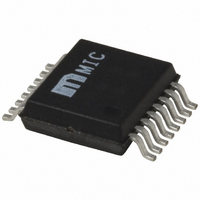
MIC2182-3.3YSM Micrel Inc, MIC2182-3.3YSM Datasheet - Page 20

MIC2182-3.3YSM
Manufacturer Part Number
MIC2182-3.3YSM
Description
IC CTRLR SYNC BUCK 3.3V 16-SSOP
Manufacturer
Micrel Inc
Type
Step-Down (Buck)r
Datasheet
1.MIC2182-5.0YSM.pdf
(28 pages)
Specifications of MIC2182-3.3YSM
Internal Switch(s)
No
Synchronous Rectifier
Yes
Number Of Outputs
1
Voltage - Output
3.3V
Current - Output
20A
Frequency - Switching
300kHz
Voltage - Input
4.5 ~ 16.5 V
Operating Temperature
-40°C ~ 85°C
Mounting Type
Surface Mount
Package / Case
16-SSOP
Power - Output
270mW
Number Of Pwm Outputs
1
On/off Pin
Yes
Adjustable Output
No
Topology
Boost/Buck
Switching Freq
330KHz
Operating Supply Voltage (max)
32V
Output Current
20mA
Output Voltage
3.3V
Synchronous Pin
Yes
Rise Time
60ns
Fall Time
60ns
Operating Temperature Classification
Industrial
Mounting
Surface Mount
Pin Count
16
Package Type
SSOP
Duty Cycle
86%
Lead Free Status / RoHS Status
Lead free / RoHS Compliant
Other names
576-2157
MIC2182-3.3YSM
MIC2182-3.3YSM
Available stocks
Company
Part Number
Manufacturer
Quantity
Price
Company:
Part Number:
MIC2182-3.3YSM
Manufacturer:
MIC
Quantity:
76
Company:
Part Number:
MIC2182-3.3YSM
Manufacturer:
MICREL
Quantity:
153
MIC2182
pins and routed with a wide trace. The capacitor should be a
good quality tantalum. An additional 1 F ceramic capacitor
may be necessary when driving large MOSFETs with high
gate capacitance. Incorrect placement of the V
capacitor will cause jitter or oscillations in the switching
waveform and large variations in the overcurrent limit.
A 0.1 F ceramic capacitor is required to decouple the VIN.
The capacitor should be placed near the IC and connected
directly to between pin 10 (Vcc) and pin 12 (PGND).
PCB Layout and Checklist
PCB layout is critical to achieve reliable, stable and efficient
performance. A ground plane is required to control EMI and
minimize the inductance in power, signal and return paths.
The following guidelines should be followed to insure proper
operation of the circuit.
M9999-042204
• Signal and power grounds should be kept
• The connection between the current-sense
separate and connected at only one location.
Large currents or high di/dt signals that occur
when the MOSFETs turn on and off must be
kept away from the small signal connections.
resistor and the MIC2182 current-sense inputs
(pin 8 and 9) should have separate traces,
routed from the terminals directly to the IC pins.
The traces should be routed as closely as
possible to each other and their length should be
minimized. Avoid running the traces under the
inductor and other switching components. A 1nF
to 0.1 F capacitor placed between pins 8 and 9
will help attenuate switching noise on the current
sense traces. This capacitor should be placed
close to pins 8 and 9.
DD
decoupling
20
• When the high-side MOSFET is switched on, the
• When the low-side MOSFET is switched on,
• The freewheeling diode, D1 in Figure 2, con-
• The 4.7 F capacitor, which connects to the VDD
• The V
critical flow of current is from the input capacitor
through the MOSFET, inductor, sense resistor,
output capacitor, and back to the input capacitor.
These paths must be made with short, wide
pieces of trace. It is good practice to locate the
ground terminals of the input and output capaci-
tors close to each.
current flows through the inductor, sense
resistor, output capacitor, and MOSFET. The
source of the low-side MOSFET should be
located close to the output capacitor.
ducts current during the dead time, when both
MOSFETs are off. The anode of the diode
should be located close to the output capacitor
ground terminal and the cathode should be
located close to the input side of the inductor.
terminal (pin 11) must be located right at the IC.
The VDD terminal is very noise sensitive and
placement of this capacitor is very critical.
Connections must be made with wide trace. The
capacitor may be located on the bottom layer of
the board and connected to the IC with multiple
vias.
close to the IC and connected between pins 10
and 12. Connections should be made with a
ground and power plane or with short, wide
trace.
IN
bypass capacitor should be located
April 22, 2004
Micrel


