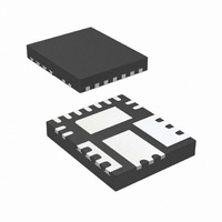
IR3843AMTR1PBF International Rectifier, IR3843AMTR1PBF Datasheet - Page 19

IR3843AMTR1PBF
Manufacturer Part Number
IR3843AMTR1PBF
Description
IC REG SYNC BUCK 3A 15-QFN
Manufacturer
International Rectifier
Series
SupIRBuck™r
Type
Step-Down (Buck)r
Datasheet
1.IR3843AMTR1PBF.pdf
(33 pages)
Specifications of IR3843AMTR1PBF
Internal Switch(s)
Yes
Synchronous Rectifier
Yes
Number Of Outputs
1
Voltage - Output
0.7 ~ 18.9 V
Current - Output
3A
Frequency - Switching
225kHz ~ 1.32MHz
Voltage - Input
1.5 ~ 21 V
Operating Temperature
-40°C ~ 125°C
Mounting Type
Surface Mount
Package / Case
15-PowerVQFN
Power - Output
682mW
Part Status
Active
Package
PQFN / 5 x 6
Circuit
Single Output
Iout (a)
3
Switch Freq (khz)
250 - 1200
Input Range (v)
1.5 - 21
Output Range (v)
0.7 - 0.9*Vin
Ocp Otp Uvlo Pre-bias Soft Start And
PGOOD + EN + SEQ
Digital Home Media
Yes
Lead Free Status / RoHS Status
Lead free / RoHS Compliant
Other names
IR3843AMTR1PBFTR
V
the voltage Vc across C6 remains approximately
unchanged and the voltage at the Boot pin
becomes
A bootstrap capacitor of value 0.1uF is suitable
for most applications.
For applications with 21V input voltage, the switch
node may ring above the 25V absolute maximum
voltage rating. To prevent
using best layout practices, it may be necessary
to provide a 10 ohm resistor in series with the
boot capacitor.
Input Capacitor Selection
The ripple current generated during the on time of
the upper MOSFET should be provided by the
input capacitor. The RMS value of this ripple is
expressed by:
Where:
D is the Duty Cycle
I
current.
Io is the output current.
For I
Ceramic capacitors are recommended due to
their peak current capabilities. They also feature
low ESR and ESL at higher frequency which
enables better efficiency. For this application, it is
RMS
Boot
Rev 13.0
o
Fig. 12. Bootstrap circuit to generate
is the RMS value of the input capacitor
=3A and D = 0.15, the I
≅
D =
I
V
RMS
in
V
V
+
=
in
o
V
I
o
..........
cc
∗
−
D
Vc voltage
V
∗
..........
D
(
1
..........
−
D
..........
)
..........
..........
RMS
this, in addition to
..
..........
(13)
= 1.07A.
..........
....(12)
..........
(11)
advisable to have 1x10uF 25V ceramic capacitors
C3216X5R1E106M from TDK. In addition to
these, although not mandatory, a 1X330uF, 25V
SMD capacitor EEV-FK1E331P may also be used
as a bulk capacitor and is recommended if the
input power supply is not located close to the
converter.
Inductor Selection
The inductor is selected based on output power,
operating frequency and efficiency requirements.
A low inductor value causes large ripple current,
resulting in the smaller size, faster response to a
load transient but poor efficiency and high output
noise. Generally, the selection of the inductor
value can be reduced to the desired maximum
ripple current in the inductor
point is usually found between 20% and 50%
ripple of the output current.
For the buck converter, the inductor value for the
desired
determined using the following relation:
V
Where:
If
calculated to be 2.13μH. Select L=2.2 μH.
The PCMB065T-2R2MS from Vishay provides a
compact, low profile inductor suitable for this
application
in
L
−
=
Δi ≈ 40%(I
V
(
V
o
in
=
−
L
V
V
operating
F
D
Δi
Δt
V
in
o
∗
s
o
=
=
=
=
=
Δ
Δ
)
=
Duty
∗
Switching
t
Inductor
i
Output
Turn
Maximum
;
V
o
in
), then the output inductor is
Δ
t
∗
cycle
IR3843AMPbF
on
V
=
Δ
o
i
ripple
Voltage
D
ripple
*
time
∗
F
frequency
input
s
F
1
s
..........
current
( i
current
voltage
Δ
)
. The optimum
..........
PD-97509
can
..........
19
.
be
(14)


