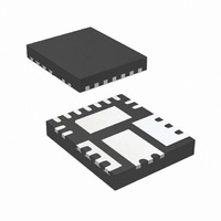
IR3841MTR1PBF International Rectifier, IR3841MTR1PBF Datasheet - Page 18

IR3841MTR1PBF
Manufacturer Part Number
IR3841MTR1PBF
Description
IC REG SYNC SUPIRBUCK 8A 5X6QFN
Manufacturer
International Rectifier
Series
SupIRBuck™r
Type
Step-Down (Buck)r
Datasheet
1.IR3841MTR1PBF.pdf
(32 pages)
Specifications of IR3841MTR1PBF
Internal Switch(s)
Yes
Synchronous Rectifier
Yes
Number Of Outputs
1
Voltage - Output
0.7 ~ 14.4 V
Current - Output
8A
Frequency - Switching
250kHz ~ 1.5MHz
Voltage - Input
1.5 ~ 16 V
Operating Temperature
-40°C ~ 125°C
Mounting Type
Surface Mount
Package / Case
15-PowerVQFN
Power - Output
1.6W
Part Status
Active
Package
PQFN / 5 x 6
Circuit
Single Output
Iout (a)
8
Switch Freq (khz)
250 - 1500
Input Range (v)
1.5 - 16
Output Range (v)
0.7 - 0.9*Vin
Ocp Otp Uvlo Pre-bias Soft Start And
PGOOD + EN + SEQ
Server Storage
Yes
Routers Switches
Yes
Base Station Telecom
Yes
Lead Free Status / RoHS Status
Lead free / RoHS Compliant
Other names
IR3841MTR1PBFTR
Available stocks
Company
Part Number
Manufacturer
Quantity
Price
Company:
Part Number:
IR3841MTR1PBF
Manufacturer:
HONY
Quantity:
4 110
Part Number:
IR3841MTR1PBF
Manufacturer:
IR
Quantity:
20 000
V
the voltage Vc across C6 remains approximately
unchanged and the voltage at the Boot pin
becomes
A bootstrap capacitor of value 0.1uF is suitable
for most applications.
Input Capacitor Selection
The ripple current generated during the on time of
the upper MOSFET should be provided by the
input capacitor. The RMS value of this ripple is
expressed by:
Where:
D is the Duty Cycle
I
current.
Io is the output current.
For I
Ceramic capacitors are recommended due to
their peak current capabilities. They also feature
low ESR and ESL at higher frequency which
enables better efficiency. For this application, it is
advisable to have 4x10uF 16V ceramic capacitors
ECJ-3YX1C106K from Panasonic. In addition to
these, although not mandatory, a 1X330uF, 25V
SMD capacitor EEV-FK1E331P may also be
used as a bulk capacitor and is recommended if
the input power supply is not located close to the
converter.
RMS
06/18/09
Boot
I
D =
RMS
o
Fig. 12. Bootstrap circuit to generate
is the RMS value of the input capacitor
=8A and D = 0.15, the I
≅
V
V
V
V
=
cc
IR3841
in
o
in
I
o
..........
+
∗
V
D
cc
∗
..........
−
(
1
Vc voltage
V
−
D
D
..........
)
..........
..........
..........
..
..........
RMS
(13)
V
PGnd
IN
= 2.86A.
C6
SW
....(12)
..........
Boot
Vc
+
-
..........
L
(11)
Inductor Selection
The inductor is selected based on output power,
operating frequency and efficiency requirements.
A low inductor value causes large ripple current,
resulting in the smaller size, faster response to a
load transient but poor efficiency and high output
noise. Generally, the selection of the inductor
value can be reduced to the desired maximum
ripple current in the inductor
point is usually found between 20% and 50%
ripple of the output current.
For the buck converter, the inductor value for the
desired
determined using the following relation:
Where:
If
calculated to be 0.91μH. Select L=1 μH.
The MPL105-1R0 from Delta provides a compact,
low profile inductor suitable for this application.
.
V
in
L
−
Δi ≈ 35%(I
=
V
(
V
V
V
o
F
D
Δi
Δt
in
in
o
s
=
=
=
operating
−
=
=
=
=
L
Duty
V
Switching
Inductor
Output
Turn
Maximum
∗
o
Δ
Δ
)
∗
t
i
cycle
o
;
V
on
), then the output inductor is
in
Δ
Voltage
t
∗
ripple
time
V
=
Δ
frequency
IR3841MPbF
ripple
o
input
i
D
*
∗
F
current
s
F
1
s
voltage
..........
current
( i
Δ
)
. The optimum
..........
can
..........
18
be
.
(14)


