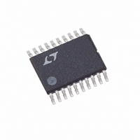
LTC1735CF#PBF Linear Technology, LTC1735CF#PBF Datasheet - Page 25

LTC1735CF#PBF
Manufacturer Part Number
LTC1735CF#PBF
Description
IC SW REG SYNC STEP-DWN 20-TSSOP
Manufacturer
Linear Technology
Type
Step-Down (Buck)r
Datasheet
1.LTC1735CSPBF.pdf
(32 pages)
Specifications of LTC1735CF#PBF
Internal Switch(s)
No
Synchronous Rectifier
Yes
Number Of Outputs
1
Voltage - Output
0.8 ~ 6 V
Current - Output
3A
Frequency - Switching
300kHz
Voltage - Input
4 ~ 30 V
Operating Temperature
0°C ~ 85°C
Mounting Type
Surface Mount
Package / Case
20-TSSOP
Lead Free Status / RoHS Status
Lead free / RoHS Compliant
Power - Output
-
Available stocks
Company
Part Number
Manufacturer
Quantity
Price
APPLICATIO S I FOR ATIO
100mV/DIV
Automotive Considerations: Plugging into the
Cigarette Lighter
As battery-powered devices go mobile, there is a natural
interest in plugging into the cigarette lighter in order to
conserve or even recharge battery packs during operation.
But before you connect, be advised: you are plugging
into the supply from hell. The main power line in an
automobile is the source of a number of nasty potential
transients, including load-dump, reverse-battery and
double-battery.
Load-dump is the result of a loose battery cable. When the
cable breaks connection, the field collapse in the alternator
can cause a positive spike as high as 60V which takes
several hundred milliseconds to decay. Reverse-battery is
just what it says, while double-battery is a consequence of
tow-truck operators finding that a 24V jump start cranks
cold engines faster than 12V.
Figure 10. Transient Response with Active Voltage Positioning
10A/DIV
10A/DIV
100mV/DIV
Figure 9. Normal Transient Response (Without R1, R4)
1.582V
1.418V
1.5V
1.5V
15A
15A
0A
0A
V
V
V
V
IN
OUT
IN
OUT
= 12V
= 12V
= 1.5V
= 1.5V
U
CURRENT
VOLTAGE
CURRENT
VOLTAGE
OUTPUT
OUTPUT
LOAD
LOAD
50 s/DIV
50 s/DIV
U
FIGURE 8 CIRCUIT
FIGURE 8 CIRCUIT
W
1735 F09
1735 F10
U
The network shown in Figure 11 is the most straight
forward approach to protect a DC/DC converter from the
ravages of an automotive power line. The series diode
prevents current from flowing during reverse-battery,
while the transient suppressor clamps the input voltage
during load-dump. Note that the transient suppressor
should not conduct during double-battery operation, but
must still clamp the input voltage below breakdown of the
converter. Although the LTC1735 has a maximum input
voltage of 36V, most applications will be limited to 30V by
the MOSFET BV
Design Example
As a design example, assume V
V
R
Assume a 3.3 H inductor and check the actual value of the
ripple current. The following equation is used:
The highest value of the ripple current occurs at the
maximum input voltage:
The maximum ripple current is 33% of maximum output
current, which is about right.
IN
SENSE
R
C
= 22V(max), V
OSC
SENSE
I
I
L
L
and C
= 1.61(10
Figure 11. Plugging into the Cigarette Lighter
( )( )
300
V
12V
GENERAL INSTRUMENT
= 50mV/5A = 0.01
f L
OUT
TRANSIENT VOLTAGE
50A I
OSC
kHz
1 8
DSS
PK
SUPPRESSOR
.
– 1
( .
can immediately be calculated:
RATING
7
3 3
V
OUT
1.5KA24A
)/(300kHz) – 11pF = 43pF
.
V
V
OUT
IN
= 1.8V, I
H
)
1
–
V
IN
1 8
22
MAX
.
V
V
= 5A and f = 300kHz.
IN
LTC1735
= 12V(nominal),
LTC1735
1 7
.
1735 F11
A
25
1735fc


