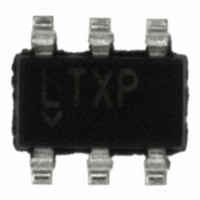
LT1934ES6#TRMPBF Linear Technology, LT1934ES6#TRMPBF Datasheet

LT1934ES6#TRMPBF
Specifications of LT1934ES6#TRMPBF
LT1934ES6#PBF
LT1934ES6#TRMPBF
LT1934ES6#TRMPBFTR
Available stocks
Related parts for LT1934ES6#TRMPBF
LT1934ES6#TRMPBF Summary of contents
Page 1
... Fast current limiting protects the LT1934 and external components against shorted outputs, even at 34V input. L, LT, LTC and LTM are registered trademarks of Linear Technology Corporation. Burst Mode is a registered trademark of Linear Technology Corporation. ThinSOT is a trademark of Linear Technology Corporation. ...
Page 2
LT1934/LT1934-1 ABSOLUTE MAXIMUM RATINGS Input Voltage (V ) ................................................... 34V IN BOOST Pin Voltage ................................................. 40V BOOST Pin Above SW Pin ........................................ 20V SHDN Pin ................................................................. 34V FB Voltage .................................................................. 6V SW Voltage ............................................................... V PIN CONFIGURATION TOP VIEW BOOST ...
Page 3
ELECTRICAL CHARACTERISTICS temperature range, otherwise specifi cations are at T SYMBOL Undervoltage Lockout Quiescent Current FB Comparator Trip Voltage FB Comparator Hysteresis FB Pin Bias Current FB Voltage Line Regulation Switch Off Time Maximum Duty Cycle Switch V CESAT Switch ...
Page 4
LT1934/LT1934-1 TYPICAL PERFORMANCE CHARACTERISTICS LT1934 Effi ciency OUT 100 LT1934 OUT L = 47μ 25° 12V 24V 0 ...
Page 5
TYPICAL PERFORMANCE CHARACTERISTICS Quiescent Current vs Temperature –50 – TEMPERATURE (°C) Minimum Input Voltage V = 3.3V OUT 6.0 LT1934 V = 3.3V OUT 5 25°C A BOOST DIODE TIED TO ...
Page 6
LT1934/LT1934-1 BLOCK DIAGRAM SHDN V ON OFF REF GND 6 + – ON TIME R Q 12μs DELAY S Q OFF TIME 1.8μs DELAY + 1.25V ENABLE – FEEDBACK COMPARATOR ...
Page 7
OPERATION (Refer to Block Diagram) The LT1934 uses Burst Mode control, combining both low quiescent current operation and high switching frequency, which result in high effi ciency across a wide range of load currents and a small total circuit size. ...
Page 8
LT1934/LT1934-1 APPLICATIONS INFORMATION Which One to Use: LT1934 or LT1934-1? The only difference between the LT1934 and LT1934-1 is the peak current through the internal switch and the inductor. If your maximum load current is less than 60mA, use the ...
Page 9
APPLICATIONS INFORMATION Table 2. Inductor Vendors VENDOR PHONE Murata (404) 426-1300 Sumida (847) 956-0666 Coilcraft (847) 639-6400 Würth (866) 362-6673 Electronics the average inductor current equals the load current, the maximum load current is – ΔI /2 ...
Page 10
LT1934/LT1934-1 APPLICATIONS INFORMATION capacitor is subject to large surge currents if the LT1934 circuit is connected to a low impedance supply, and that some electrolytic capacitors (in particular tantalum) must be specifi ed for such use. Output Capacitor and Output ...
Page 11
APPLICATIONS INFORMATION when used with ceramic capacitors will be lower and may be acceptable. A fi nal precaution regarding ceramic capacitors concerns the maximum input voltage rating of the LT1934. A ceramic input capacitor combined with trace or cable inductance ...
Page 12
LT1934/LT1934-1 APPLICATIONS INFORMATION Minimum Input Voltage V 6.0 LT1934 V = 3.3V OUT 5 25°C A BOOST DIODE TIED TO OUTPUT 5 START IN 4.5 4 RUN IN 3.5 3.0 0 LOAD ...
Page 13
... GND (5c) VIAS TO LOCAL GROUND PLANE OUTLINE OF LOCAL GROUND PLANE is plugged into a live supply (see Linear Technology Application Note 88 for a complete discussion). The low loss ceramic capacitor combined with stray inductance in series with the power source forms an under damped tank circuit, and the voltage at the V ring to twice the nominal input voltage, possibly exceeding the LT1934’ ...
Page 14
LT1934/LT1934-1 APPLICATIONS INFORMATION Figure 7 shows the waveforms that result when an LT1934 circuit is connected to a 24V supply through six feet of 24-gauge twisted pair. The fi rst plot is the response with a 2.2μF ceramic capacitor at ...
Page 15
APPLICATIONS INFORMATION in series with the input to eliminate the voltage overshoot (it also reduces the peak input current). A 0.1μF capacitor improves high frequency fi ltering. This solution is smaller and less expensive than the electrolytic capacitor. For high ...
Page 16
LT1934/LT1934-1 TYPICAL APPLICATIONS 4.5V TO 34V 6.5V TO 34V 16 3.3V Step-Down Converter 0.1μF BOOST LT1934-1 1μF 10pF SHDN ON OFF FB GND C1: TAIYO YUDEN JMK316BJ226ML C2: TAIYO YUDEN GMK316BJ105ML D1: ZETEX ...
Page 17
TYPICAL APPLICATIONS 3.6V TO 16V ON OFF Loop Powered 3.3V Supply with Additional Isolated Output V IN 14V TO 32V <3.6mA 1.8V Step-Down Converter D2 0.1μF L1 BOOST 33μ LT1934 2.2μF 147k SHDN ...
Page 18
LT1934/LT1934-1 TYPICAL APPLICATIONS 28V C2 1μF + C1: SANYO 6TPB47M C2: TAIYO YUDEN GMK316BJ105ML D1, D3: ON SEMICONDUCTOR MBR0540 D2: CENTRAL CMDSH-3 L1: SUMIDA CR43-470 15V TO 32V ON OFF 18 Standalone 350mA Li-Ion Battery ...
Page 19
PACKAGE DESCRIPTION 0.62 MAX 3.85 MAX 2.62 REF RECOMMENDED SOLDER PAD LAYOUT PER IPC CALCULATOR 0.20 BSC DATUM ‘A’ NOTE: 1. DIMENSIONS ARE IN MILLIMETERS 2. DRAWING NOT TO SCALE 3. DIMENSIONS ARE INCLUSIVE OF PLATING 4. DIMENSIONS ARE EXCLUSIVE ...
Page 20
... OUT 1.2V 2.5mA 25μA, OUT 0.8V 20μA, I < 1μA, OUT 0.6V 20μA, I < 1μA, OUT 0.8V 60μA, I < 1μA, OUT 0.8V 60μA, I < 1μA, OUT 1.2V 2.5mA 30μA, OUT 0209 REV E • PRINTED IN USA © LINEAR TECHNOLOGY CORPORATION 2002 1934fe ...


