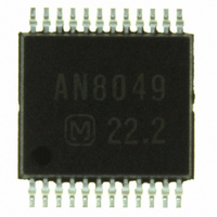
AN8049SH-E1 Panasonic - SSG, AN8049SH-E1 Datasheet - Page 6

AN8049SH-E1
Manufacturer Part Number
AN8049SH-E1
Description
IC MULTI CONFIG 40MA SSOP24D
Manufacturer
Panasonic - SSG
Type
Step-Down (Buck), Step-Up (Boost), Invertingr
Specifications of AN8049SH-E1
Internal Switch(s)
Yes
Synchronous Rectifier
No
Number Of Outputs
3
Current - Output
40mA
Frequency - Switching
20kHz ~ 1MHz
Voltage - Input
1.8 ~ 14 V
Operating Temperature
-30°C ~ 85°C
Mounting Type
Surface Mount
Package / Case
24-SSOP
Power - Output
146mW
Lead Free Status / RoHS Status
Contains lead / RoHS non-compliant
Voltage - Output
-
Other names
AN8049SHE1
AN8049SHE1TR
AN8049SHE1TR
Available stocks
Company
Part Number
Manufacturer
Quantity
Price
Company:
Part Number:
AN8049SH-E1V
Manufacturer:
MITSUMI
Quantity:
2 511
Part Number:
AN8049SH-E1V
Manufacturer:
PANASONIC/松下
Quantity:
20 000
AN8049FHN
I Terminal Equivalent Circuits
6
Pin No.
1
2
3
4
20 kΩ
20 kΩ
3
4
50 kΩ
1.1 µA
1.1 µA
50 kΩ
2
Equivalent circuit
1
1.26 V
1.26 V
7
7
50 kΩ
V
V
50 kΩ
22
20
CC
CC
15
High
channel 3 operation
is turned off.
High
channel 2 operation
is turned off.
15
PWM1
PWM2
SDH000011BEB
DT2:
Sets the channel 2 soft start time.
Set the time by connecting a capacitor between
this pin and ground.
Note that although the channel 2 maximum on
duty is set internally to 86%, the maximum on
duty can be set to a value of 86% or less by
inserting a resistor between this pin and ground,
and can be set to a value of 86% or more by inse-
rting a resistor between this pin and the V
DT1:
Sets the channel 1 soft start time.
Set the time by connecting a capacitor between
this pin and ground.
Note that although the channel 1 maximum on
duty is set internally to 86%, the maximum on
duty can be set to a value of 86% or less by
inserting a resistor between this pin and ground,
and can be set to a value of 86% or more by inse-
rting a resistor between this pin and the V
CTL3:
Controls the on/off state of channel 3.
A delay can be provided in the power supply
turn-on start time by connecting a capacitor
between this pin and ground.
t
This pin can also be used to control the on/off
state with an external signal.
In that case, the allowable input voltage range is
from 0 V to V
timer latch operation, this pin is connected to
ground through a 20 kΩ resistor.
CTL2:
Controls the on/off state of channel 2.
A delay can be provided in the power supply
turn-on start time by connecting a capacitor
between this pin and ground.
t
This pin can also be used to control the on/off
state with an external signal.
In that case, the allowable input voltage range is
from 0 V to V
timer latch operation, this pin is connected to
ground through a 20 kΩ resistor.
DLY3
DLY2
= 1.26 (V) × C
= 1.26 (V) × C
CC
CC
. Note that during U.V.L.O. and
. Note that during U.V.L.O. and
Description
CTL3
CTL2
(µF)/1.1 (µA) (s)
(µF)/1.1 (µA) (s)
REF
REF
pin.
pin.
I/O
I
I
I


