IRU3013CW International Rectifier, IRU3013CW Datasheet
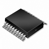
IC CNTRL 5BIT TRPL LDO 24-SOIC

IRU3013CW

Manufacturer Part Number
IRU3013CW
Description
IC CNTRL 5BIT TRPL LDO 24-SOIC
Manufacturer
International Rectifier
Datasheet

Specifications of IRU3013CW

Applications
Controller, Intel Pentium® III
Voltage - Input
5V, 12V
Number Of Outputs
4
Voltage - Output
1.05 ~ 1.83 V
Operating Temperature
0°C ~ 70°C
Mounting Type
Surface Mount
Package / Case
24-SOIC (7.5mm Width)
Lead Free Status / RoHS Status
Contains lead / RoHS non-compliant
Other names
*IRU3013CW

Available stocks

Company
Part Number
Manufacturer
Quantity
Price
Part Number:
IRU3013CW
Manufacturer:
IR
Quantity:
20 000
FEATURES
APPLICATIONS
TYPICAL APPLICATION
PACKAGE ORDER INFORMATION
Rev. 1.4
08/20/02
Meets Latest VRM 8.5 Specification
Provides Single Chip Solution for Vcore, 1.2V AGTL+,
1.8V and V
On-Board 5-Bit DAC and Decoder programs the out-
put voltage from 1.050V to 1.825V
Loss-less Short Circuit Protection
Synchronous operation allows maximum efficiency
Patented architecture allows fixed frequency opera-
tion as well as 100% duty cycle when operating with
a changing load
Minimum Part Count, No External Compensation
Soft-Start
High current totem pole driver for directly driving an
external Power MOSFET
Power Good Function
Pentium III with VRM 8.5 Specification
DC to DC Converters
VRM 8.5 COMPATIBLE 5-BIT PROGRAMMABLE SYNCHRONOUS
V
V
OUT
OUT
3.3V
2
3
BUCK CONTROLLER IC WITH TRIPLE LDO CONTROLLER
DDQ
T
0 To 70
0 To 70
A
(°C)
Figure 1 - Typical application of IRU3013.
Note: Pentium III is trade mark of Intel Corp.
IRU3013CQ
IRU3013CW
CONTROL
CONTROL
IRU3013
DEVICE
LINEAR
LINEAR
www.irf.com
24-Pin Plastic QSOP NB (Q)
24-Pin Plastic SOIC WB (W)
VRM 8.5 VID
SWITCHER
DESCRIPTION
The IRU3013 controller IC is specifically designed for
Intel Pentium III
scribed in the VRM 8.5 specification. The IC provides
a single chip solution for the Vcore, 1.2V AGTL+,
1.8V and a third uncommitted LDO controller that
can be used either as 1.2V power good detector or
to provide 1.5V AGP bus in applications that this
voltage is required. The IRU3013 features a patented
topology that, in combination with a few external com-
ponents, (*Note: See application current in Figure 3) will
provide in excess of 30A of output current for an on-
board Vcore synchronous converter while automatically
providing the output voltage specified in VRM 8.5 speci-
fication. The IRU3013 also features, loss-less current
sensing by using the R
MOSFET as the sensing resistor, a Power Good win-
dow comparator that switches its open collector output
low when the output is outside of a 10% window. Other
features of the device are: Under-voltage lockout for both
5V and 12V supplies, an external programmable soft-
start function, and the ability to program the oscillator
frequency by connecting an external capacitor.
CONTROL
CONTROL
LINEAR
PACKAGE
microprocessor applications as de-
5V
DS(ON)
Data Sheet No. PD94249
of the high side Power
IRU3013
V
V
OUT
OUT
1
4
1

Related parts for IRU3013CW

IRU3013CW Summary of contents

Page 1

... IRU3013 LINEAR LINEAR CONTROL CONTROL Figure 1 - Typical application of IRU3013. Note: Pentium III is trade mark of Intel Corp. DEVICE PACKAGE IRU3013CQ 24-Pin Plastic QSOP NB (Q) IRU3013CW 24-Pin Plastic SOIC WB (W) www.irf.com Data Sheet No. PD94249 IRU3013 microprocessor applications as de- of the high side Power DS(ON ...

Page 2

IRU3013 ABSOLUTE MAXIMUM RATINGS V5 Supply Voltage .................................................... 10V V12 Supply Voltage .................................................. 20V All Other Pins .......................................................... 7V Storage Temperature Range ...................................... -65°C To 150°C Operating Junction Temperature Range ..................... PACKAGE INFORMATION 24-PIN PLASTIC QSOP ( ...

Page 3

PARAMETER SYM UVLO Section UVLO Threshold - 12V UVLO Hysteresis - 12V UVLO Threshold - 5V UVLO Hysteresis - 5V Error Comparator Section Input Offset Voltage Delay to Output Current Limit Section CS Threshold Set Current CS Comp Offset Voltage ...

Page 4

IRU3013 PIN DESCRIPTIONS PIN# PIN SYMBOL PIN DESCRIPTION 1 Ct This pin programs the oscillator frequency in the range of 50 KHz to 500KHz by means of an external capacitor connected from this pin to the ground. 2 Lin1 Controls ...

Page 5

BLOCK DIAGRAM Enable V12 14 UVLO V5 5 Vset D0 23 Enable D1 5Bit 22 DAC Ctrl Logic D3 20 D25 Lin1 2 1.2V Lin2 0.8V Lin4 16 ...

Page 6

IRU3013 TYPICAL APPLICATION IR WORLD HEADQUARTERS: 233 Kansas St., El Segundo, California 90245, USA Tel: (310) 252-7105 6 Visit us at www.irf.com for sales contact information Data and specifications subject to change without notice. 02/01 www.irf.com TAC Fax: (310) 252-7903 ...

Page 7

QSOP Package, Narrow Body A B PIN NO. 1 NOTE: ALL MEASUREMENTS ARE IN MILLIMETERS. Rev. 1.4 08/20/02 24-Pin D E DETAIL 0.36 0. 24-PIN SYMBOL MIN MAX A 8.55 ...

Page 8

IRU3013 24-Pin Surface Mount, Wide Body PIN NO. 1 NOTE: ALL MEASUREMENTS ARE IN MILLIMETERS. 8 (W) SOIC Package C E DETAIL 0.51 0.020 SYMBOL 24-PIN MIN MAX ...

Page 9

PACKAGE SHIPMENT METHOD PKG PACKAGE DESIG DESCRIPTION Q QSOP Plastic, Narrow Body W SOIC, Wide Body 1 1 Feed Direction Figure A IR WORLD HEADQUARTERS: 233 Kansas St., El Segundo, California 90245, USA Tel: (310) 252-7105 Rev. 1.4 08/20/02 PIN ...

Related keywords