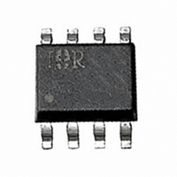
IRU3033CS International Rectifier, IRU3033CS Datasheet - Page 2

IRU3033CS
Manufacturer Part Number
IRU3033CS
Description
IC CTRL/REG PWM SWITCH 8-SOIC
Manufacturer
International Rectifier
Datasheet
1.IRU3033CSTR.pdf
(12 pages)
Specifications of IRU3033CS
Applications
Controller, Intel Pentium®, II, P55C
Voltage - Input
12V
Number Of Outputs
1
Voltage - Output
2 ~ 3.5 V
Operating Temperature
0°C ~ 70°C
Mounting Type
Surface Mount
Package / Case
8-SOIC (3.9mm Width)
Lead Free Status / RoHS Status
Contains lead / RoHS non-compliant
Other names
*IRU3033CS
IRU3033-CS
IRU3033-CS
IRU3033-CS
IRU3033-CS
Available stocks
Company
Part Number
Manufacturer
Quantity
Price
Part Number:
IRU3033CS
Manufacturer:
IR
Quantity:
20 000
Part Number:
IRU3033CSDTR
Manufacturer:
IR
Quantity:
20 000
Part Number:
IRU3033CSTR
Manufacturer:
IR
Quantity:
20 000
IRU3033(PbF)
ABSOLUTE MAXIMUM RATINGS
V
Fb Pin Voltages ........................................................ -0.3V To 5V
Storage Temperature Range ...................................... -65°C To 150°C
Operating Junction Temperature ................................
PACKAGE INFORMATION
ELECTRICAL SPECIFICATIONS
Unless otherwise specified, the following specification applies over V
cycle pulse testing is used which keeps junction and case temperatures equal to the ambient temperature.
PARAMETER
Linear Controller Section
Fb Voltage Initial Accuracy
Fb Voltage Total Variation
Fb Voltage Line Regulation
Fb Input Bias Current
Maximum Drive Current
V
Switching Controller Section
Fb Voltage Initial Accuracy
Fb Voltage Total Variation
Fb Voltage Line Regulation
Fb Input Bias Current
Min On Time
Min Off Time
V
V
Supply Current
Maximum Duty Cycle
Minimum Duty Cycle
Gate Drive Rise/Fall Time
2
12
12
HYST
HYST
,V
Supply Current
12(SW)
Pin Output-HI
Pin Output-LO
V
8-PIN PLASTIC SOIC (S)
V
12(SW)
Drv1
V
HYST
Supply Voltages .......................................
FB1
θ
1
2
3
4
JA
TOP VIEW
=160 C/W
8
7
6
5
V
Drv2
V
Gnd
12
FB2
I
DRV(max)
SYM
I
V
D
D
V
V
12(SW)
I
I
I
GATE
FB2
FB1
MAX
FB2
12
FB1
MIN
T
Drv2=V
10<V
V
V
V
T
V
V
time and 2µs off time
V
time and 2µs on time
I
I
V
V
V
Load=IRL3303
SOURCE
SINK
J
J
FB2
FB2
FB2
FB1
FB1
FB1
FB1
FB1
FB1
=25 C, Drv2=V
=25 C
=500µA, V
=1.25V
=1.25V
=1V
=1.5V
=1V, V
=1V, V
=1V, V
is sq wave with 300ns on
is sq wave with 300ns off
12
=500µA, V
<14V, Drv2=V
TEST CONDITION
FB2
www.irf.com
, C
FB1
FB2
FB1
L
=100µF
=1.5V
=1.5V, I
=1.5V
FB1
20V
0°C To 150°C
FB2
=1V
FB1
, C
=1.5V
FB2
DRV2
L
=100µF
, C
=0
L
=100µF
12
=V
12(SW)
=12V and T
1.237
1.225
1.237
1.225
MIN
11
-1
-1
0
1.250
1.250
1.250
1.250
TYP
800
800
0.2
0.2
A
50
10
70
5
=0 to 70°C. Low duty
MAX
1.262
1.275
1.262
1.275
100
+1
+1
1
UNITS
mA
mA
mA
µA
µA
ns
ns
ns
%
%
%
%
V
V
V
V
V
V


