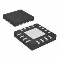
MAX1889ETE+ Maxim Integrated Products, MAX1889ETE+ Datasheet - Page 13

MAX1889ETE+
Manufacturer Part Number
MAX1889ETE+
Description
IC PWR SUP TRPL LCD 16-TQFN
Manufacturer
Maxim Integrated Products
Datasheet
1.MAX1889ETET.pdf
(32 pages)
Specifications of MAX1889ETE+
Applications
Controller, TFT, LCD
Voltage - Input
2.7 ~ 5.5 V
Number Of Outputs
3
Voltage - Output
2.7 ~ 13 V
Operating Temperature
0°C ~ 85°C
Mounting Type
Surface Mount
Package / Case
16-TQFN Exposed Pad
Lead Free Status / RoHS Status
Lead free / RoHS Compliant
The standard application circuit (Figure 1) of the
MAX1889 generates +9V, +20V, and -7V outputs for
TFT LCD displays. The input voltage is from 2.7V to
5.5V. Table 1 lists the recommended component
options and Table 2 lists the component suppliers.
Table 1. Component List
Table 2. Component Suppliers
Coilcraft
Fairchild
Taiyo Yuden
Toshiba
DESIGNATION
C4, C5, C6
D2, D3, D4
C2, C3
Q1
Q2
D1
D5
L1
P1
SUPPLIER
Standard Application Circuit
3.3µF, 6.3V X5R ceramic capacitors (0805)
Taiyo Yuden JMK212BJ335MG
4.7µF, 10V X7R ceramic capacitors (1210)
Taiyo Yuden LMK352BJ475MF
1.0A, 30V Schottky diode (S-flat)
Toshiba CRS02
200mA, 25V dual-series Schottky diodes
(SOT23)
Fairchild BAT54S
250mA, 75V switching diode (SOT23)
Central Semiconductor CMPD914
6.8µH, 1.3A inductor
Coilcraft LPO2506IB-682
2.4A, 20V P-channel MOSFET
(3-pin SuperSOT)
Fairchild FDN304P
200mA, 40V NPN bipolar transistor (SOT23)
Fairchild MMBT3904
200mA, 40V PNP bipolar transistor (SOT23)
Fairchild MMBT3906
______________________________________________________________________________________
Triple-Output TFT LCD Power Supply
DESCRIPTION
847-639-6400
408-822-2000
800-348-2496
949-455-2000
PHONE
The MAX1889 contains a high-performance, step-up
switching regulator, two low-cost linear-regulator con-
trollers, and multiple levels of protection circuitry. Figure
2 shows the system functional diagram of the device.
The output voltage of the main step-up converter (V
can be set from V
age-divider. The high switching frequency (500kH/1MHz)
of the main step-up converter and current-mode control
provide fast transient response and allow the use of low-
profile inductors and ceramic capacitors. The internal
power MOSFET minimizes the external component count
while achieving high efficiency by incorporating a loss-
less current-sensing technology.
The switching node (LX) can generate both positive
and negative voltage supplies by driving charge-pump
stages of capacitors and diodes. The user can use as
many charge-pump stages as needed to generate sup-
ply voltages of more than +30V and -15V. The positive
and negative linear-regulator controllers postregulate
the charge-pump supply voltages and allow users to
program power-up sequencing as well.
The unique input switch control of the MAX1889 senses
the current drawn from the input power supply by moni-
toring the voltage drop across the input P-channel
MOSFET and latches off if an overcurrent condition
lasts for more than the fault timer period. In addition, all
three outputs are monitored for fault conditions that last
longer than the fault latch timer. If the junction tempera-
ture of the IC exceeds +160°C, the device goes into a
latched shutdown state.
The main step-up regulator switches at 1MHz (or 500kHz)
and employs a current-mode control architecture to
maximize loop bandwidth to provide fast-transient
response to pulsed loads found in source drivers for TFT
LCD panels. Also, the high switching frequency allows
the use of low-profile inductors and capacitors to
minimize the thickness of LCD panel designs. The
integrated high-efficiency MOSFET and the IC’s built-in
soft-start function reduce the number of external com-
ponents required while controlling inrush current.
with Fault Protection
847-639-1469
408-822-2102
847-925-0899
949-859-3963
FAX
IN
to 13V with an external resistive volt-
Detailed Description
Main Step-Up Regulator
www.coilcraft.com
www.fairchildsemi.com
www.t-yuden.com
www.toshiba.com
WEBSITE
MAIN
13
)


