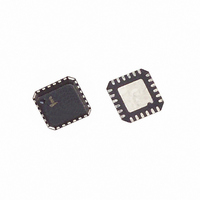
ISL6563IRZ Intersil, ISL6563IRZ Datasheet - Page 13

ISL6563IRZ
Manufacturer Part Number
ISL6563IRZ
Description
IC CNTRLR PWM 2-PH BUCK 24-QFN
Manufacturer
Intersil
Datasheet
1.ISL6563IR.pdf
(19 pages)
Specifications of ISL6563IRZ
Applications
Controller, Intel VRM9, VRM10, and AMD Hammer Applications
Voltage - Input
5 ~ 12 V
Number Of Outputs
1
Voltage - Output
0.8 ~ 1.85 V
Operating Temperature
-40°C ~ 85°C
Mounting Type
Surface Mount
Package / Case
24-VQFN Exposed Pad, 24-HVQFN, 24-SQFN, 24-DHVQFN
Lead Free Status / RoHS Status
Lead free / RoHS Compliant
Available stocks
Company
Part Number
Manufacturer
Quantity
Price
Company:
Part Number:
ISL6563IRZ
Manufacturer:
Intersil
Quantity:
300
schematic in Figure 6 demonstrates coordination of the
ISL6563 with such a rail; the resistor components are
chosen to enable the ISL6563 as the 12V input exceeds
approximately 9.75V. Additionally, an open-drain or open-
collector device can be used to wire-AND a second (or
multiple) control signal, as shown in Figure 6. To defeat the
threshold-sensitive enable, connect ENLL to VCC directly or
via a pull-up resistor.
The ‘11111’ VID code is reserved as a signal to the controller
that no load is present. The controller is disabled while
receiving this VID code and will subsequently start up upon
receiving any other code.
In summary, for the ISL6563 to operate, the following
conditions need be met: VCC and PVCC must be greater
than their respective POR thresholds, the voltage at ENLL
must be greater than 0.61V, and VID has to be different than
‘11111’. Once all these conditions are met, the controller
immediately initiates a soft start sequence.
SOFT-START
The soft-start function allows the converter to bring up the
output voltage in a controlled fashion, resulting in a linear
ramp-up. Following a delay of 16 PHASE clock cycles (about
70μs) between enabling the chip and the start of the ramp,
the output voltage progresses at a fixed rate of 12.5mV per
16 PHASE clock cycles.
Thus, the soft-start period (not including the 70µs wait) up to
a given voltage, V
where V
switching frequency (typically 222kHz).
The ISL6563 also has the ability to start up into a pre-charged
output, without causing any unnecessary disturbance. The FB
pin is monitored during soft-start, and should it be higher than
the equivalent internal ramping reference voltage, the output
drives hold both MOSFETs off. Once the internal ramping
reference exceeds the FB pin potential, the output drives are
enabled, allowing the output to ramp from the pre-charged level
to the final level dictated by the DAC setting. Should the output
be pre-charged to a level exceeding the DAC setting, the output
drives are enabled at the end of the soft-start period, leading to
an abrupt correction in the output voltage down to the DAC-set
level.
General Application Design Guide
This design guide is intended to provide a high-level
explanation of the steps necessary to create a multiphase
power converter. It is assumed that the reader is familiar with
many of the basic skills and techniques referenced below. In
addition to this guide, Intersil provides complete reference
designs that include schematics, bills of materials, and
T
SS
=
V
---------------------------------
DAC
DAC
f
S
⋅
is the DAC-set VID voltage, and f
1280
DAC
, can be approximated by Equation 9:
13
S
is the
(EQ. 9)
ISL6563
example board layouts for all common microprocessor
applications.
MOSFETs
Given the fixed switching frequency of the ISL6563 and the
integrated output drives, the selection of MOSFETs revolves
closely around the current each MOSFET is required to
conduct, the capability of the devices to dissipate heat, as well
as the characteristics of available heat sinking. Since the
ISL6563 drives the MOSFETs with 5V, the selection of
appropriate MOSFETs should be done by comparing and
evaluating their characteristics at this specific V
voltage.
LOWER MOSFET POWER CALCULATION
Since virtually all of the heat loss in the lower MOSFET is
conduction loss (due to current conducted through the channel
resistance, r
in the lower MOSFET can be found in Equation 10:
where: I
the peak-to-peak inductor current, and D is the duty cycle
(approximately V
An additional term can be added to the lower-MOSFET loss
equation to account for additional loss accrued during the
dead time when inductor current is flowing through the
lower-MOSFET body diode. This term is dependent on the
diode forward voltage at I
frequency, f
the beginning and the end of the lower-MOSFET conduction
interval, respectively.
P
P
GND>
GND>
LMOS1
LMOS 2
FIGURE 7. SOFT-START WAVEFORMS FOR ISL6563-BASED
OUTPUT PRECHARGED
M
=
BELOW DAC LEVEL
=
is the maximum continuous output current, I
r
S
V
DS(ON)
DS ON
OUTPUT PRECHARGED
; and the length of dead times, t
D ON
MULTIPHASE CONVERTER
(
ABOVE DAC LEVEL
(
OUT
T1
)
)
), a quick approximation for heat dissipated
f
S
T2
⎛
⎜
⎝
I
------------ -
/V
OUT
⎛
⎜
⎝
2
I
------------ -
IN
OUT
2
M
).
⎞
⎟
⎠
2
, V
(
+
1 D
D(ON)
I
-------- -
–
PP
2
⎞
⎟
⎠
)
+
t
d1
T3
; the switching
I
------------------------------- -
L PP
,
+
2
⎛
⎜
⎝
12
(
I
------------ -
OUT
1 D
2
V
–
OUT
d1
ENLL (5V/DIV)
–
GS
)
and t
I
-------- -
PP
(0.5V/DIV)
2
bias
June 10, 2010
⎞
⎟
⎠
(EQ. 10)
t
d2
d2
(EQ. 11)
L,PP
FN9126.8
, at
is


