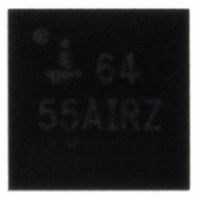
ISL6455AIRZ-TK Intersil, ISL6455AIRZ-TK Datasheet - Page 4

ISL6455AIRZ-TK
Manufacturer Part Number
ISL6455AIRZ-TK
Description
IC REG TRPL SYNCH DUAL LDO 24QFN
Manufacturer
Intersil
Datasheet
1.ISL6455IRZ-TK.pdf
(12 pages)
Specifications of ISL6455AIRZ-TK
Applications
Converter, FPGAs
Voltage - Input
4.2 ~ 5.5 V
Number Of Outputs
3
Voltage - Output
0.8 ~ 3.3 V
Operating Temperature
-40°C ~ 85°C
Mounting Type
Surface Mount
Package / Case
24-VQFN Exposed Pad, 24-HVQFN, 24-SQFN, 24-DHVQFN
Lead Free Status / RoHS Status
Lead free / RoHS Compliant
Other names
ISL6455AIRZ-TKTR
Available stocks
Company
Part Number
Manufacturer
Quantity
Price
Company:
Part Number:
ISL6455AIRZ-TK
Manufacturer:
Intersil
Quantity:
2 100
Absolute Maximum Ratings
Supply Voltage V IN , PV
Max Continuous Output Current . . . . . . . . . . . . . . . . . . . . . . 600mA
Operating Conditions
Temperature Range . . . . . . . . . . . . . . . . . . . . . . . . . . .-40°C to 85°C
CAUTION: Stresses above those listed in “Absolute Maximum Ratings” may cause permanent damage to the device. This is a stress only rating and operation of the
device at these or any other conditions above those indicated in the operational sections of this specification is not implied.
NOTE:
Electrical Specifications
V
VIN_PWM Supply Voltage Range
VIN_LDO Supply Voltage Range
Operating Supply Current (Note 3) for ISL6455
Operating Supply Current (Note 3) for ISL6455A V
Shutdown Supply Current
ISL6455 and ISL6455A
Input Bias Current (EN pin)
VIN_PWM UVLO Threshold for ISL6455
VIN_PWM UVLO Threshold for ISL6455A
VIN_LDO UVLO Threshold for ISL6455 and
ISL6455A
Thermal Shutdown Temperature (Note 6)
Thermal Shutdown Hysteresis (Note 6)
SYNCHRONOUS BUCK PWM REGULATOR
Output Voltage
FB_PWM Initial Voltage Accuracy (Note 7)
FB_PWM Line Regulation
FB_PWM Load Regulation
Peak Output Current Limit
PMOS r
NMOS r
1. θ
2. For θ
CC
Tech Brief TB379.
JA
SUPPLY
is measured in free air with the component mounted on a high effective thermal conductivity test board with “direct attach” features. See
DS(ON)
DS(ON)
JC
, the “case temp” location is the center of the exposed metal pad on the package underside.
PARAMETER
CC
, V IN _LDO. . . . . . . . GND -0.3V to +6.0V
4
Recommended operating conditions unless otherwise noted. V
5.0V for the ISL6455A, Compensation Capacitors = 33nF for LDO1 and LDO2. T
values are at T
(Note 1)
A
ISL6455
ISL6455A
V
f
f
EN = EN_LDO = GND
EN = EN_LDO = GND/V
V
V
V
V
V
V
Rising Threshold
ISL6455
ISL6455A
V
I
or 4.2-5.5V (6455A)
I
or 4.2-5.5V (ISL6455A)
I
I
= 25°C.
SW
SW
O
O
OUT
OUT
IN
IN
TR
TF
TR
TF
TR
TF
REF
= 3mA, V
= 3mA to 500mA, V
= V
= V
= 750kHz, C
= 750kHz, C
= 200mA
= 200mA
= 0.45V, I
ISL6455, ISL6455A
IN
IN
_LDO = PV
_LDO = PV
IN
= PV
OUT
TEST CONDITIONS
OUT
OUT
CC
= 3mA, T
CC
CC
= 10µF, I
= 10µF, I
IN
= 3.0-3.6V (ISL6455)
IN
= PV
= 3.3V
= 5.0V
Thermal Information
Thermal Resistance (Typical)
Maximum Junction Temperature (Plastic Package) . -55°C to 150°C
Maximum Storage Temperature Range . . . . . . . . . . . -65°C to 150°C
Maximum Lead Temperature (Soldering 10s) . . . . . . . . . . . . . 300°C
24 Ld QFN (Note 1) . . . . . . . . . . . . . . .
(Lead Tips Only)
CC
A
L
L
= -40°C to 85°C
= 0mA
= 0mA
= 3.0-3.6V (ISL6455)
IN
= V
IN
_LDO = PV
700mA
2.55
2.51
3.94
3.78
2.46
2.53
MIN
-1.5
-0.9
-0.5
-1.1
3.0
4.2
3.0
0.8
0.8
-
-
-
-
-
-
-
A
= -40°C to 85° (Note 2), typical
CC
TYP
2.65
2.56
4.05
3.89
2.64
2.59
150
170
= 3.3V for ISL6455 and
3.3
5.0
2.5
3.5
1.0
20
50
5
θ
-
-
-
-
-
-
-
JA
(°C/W)
42
MAX
1300
2.71
2.61
4.13
3.97
2.82
2.66
+1.1
3.6
5.5
5.5
3.1
4.5
1.5
2.5
3.3
0.9
0.5
10
December 21, 2005
-
-
-
-
θ
JC
UNITS
FN9196.0
(°C/W)
mΩ
mΩ
6
mA
mA
mA
µA
µA
°C
°C
%
%
%
V
V
V
V
V
V
V
V
V
V
V


