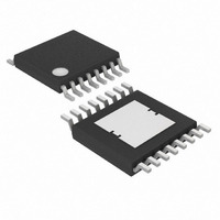
MAX5068BAUE+T Maxim Integrated Products, MAX5068BAUE+T Datasheet - Page 10

MAX5068BAUE+T
Manufacturer Part Number
MAX5068BAUE+T
Description
IC CNTRLR PWM CRNT MD 16TSSOP
Manufacturer
Maxim Integrated Products
Datasheet
1.MAX5068FAUE.pdf
(20 pages)
Specifications of MAX5068BAUE+T
Pwm Type
Current Mode
Number Of Outputs
1
Frequency - Max
1.25MHz
Duty Cycle
50%
Voltage - Supply
10.8 V ~ 24 V
Buck
No
Boost
No
Flyback
Yes
Inverting
No
Doubler
No
Divider
No
Cuk
No
Isolated
Yes
Operating Temperature
-40°C ~ 125°C
Package / Case
16-TSSOP Exposed Pad, 16-eTSSOP, 16-HTSSOP
Frequency-max
1.25MHz
Duty Cycle (max)
50 %
Output Current
1000 mA
Mounting Style
SMD/SMT
Switching Frequency
25 KHz to 1250 KHz
Maximum Operating Temperature
+ 125 C
Minimum Operating Temperature
- 40 C
Synchronous Pin
Yes
Topology
Flyback, Forward
Lead Free Status / RoHS Status
Lead free / RoHS Compliant
Use the MAX5068C/D/E/F in forward converter applica-
tions with greater than 50% duty cycle. The large duty
cycle results in much lower operating primary RMS cur-
rent through the MOSFET switch and, in most cases,
requires a smaller output filter capacitor. The major dis-
advantage to this is that the MOSFET voltage rating
must be higher. The MAX5068C/D/E/F capacitor
adjustable-slope-compensation feature allows for easy
stabilization of the inner current loop.
The MAX5068 features an input voltage UVLO/EN func-
tion to enable the PWM controller before any operation
can begin. The MAX5068C/E shut down if the voltage
at UVLO/EN falls below its 1.18V threshold. The
MAX5068A/B/D/F also incorporate an UVLO hysteresis
input to set the desired turn-off voltage.
High-Frequency, Current-Mode PWM Controller
with Accurate Programmable Oscillator
Figure 1. Nonisolated Power Supply with Programmable Input Supply Voltage
10
______________________________________________________________________________________
V
IN
R2
C2
C3
C4
Undervoltage Lockout
R3
R4
C1
FLTINT
V
REG5
RT
DT
SYNC
CC
R1
AGND
MAX5068A
D2
IN
UVLO/EN
PGND
COMP
NDRV
HYST
CS
FB
R5
The MAX5068C/E have an input voltage UVLO/EN with
a 1.231V threshold. Before any operation can com-
mence, the UVLO/EN voltage must exceed the 1.231V
threshold. The UVLO circuit keeps the PWM compara-
tor, ILIM comparator, oscillator, and output driver shut
down to reduce current consumption (see the
Functional Diagram).
Calculate R6 in
where V
and V
value in the 20kΩ range.
After a successful startup, the MAX5068C/E shut down if
the voltage at UVLO/EN drops below its 1.18V threshold.
C5
R6
R
R7
ON
HYST
ULR2
is the desired startup voltage. Choose an R7
is the UVLO/EN’s 1.231V rising threshold
R
Q1
R
6
Figure 2 by using the following formula:
CS
=
⎛
⎜
⎝
MAX5068C/E UVLO Adjustment
V
V
ULR
ON
D1
2
−
1
⎞
⎟ ×
⎠
R8
R9
R
7
C6
VOUT


