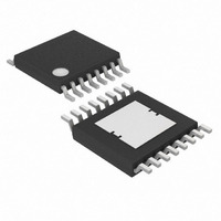
MAX15005AAUE+T Maxim Integrated Products, MAX15005AAUE+T Datasheet - Page 12

MAX15005AAUE+T
Manufacturer Part Number
MAX15005AAUE+T
Description
IC PWR SUPPLY CNTRLR 16-TSSOP
Manufacturer
Maxim Integrated Products
Datasheet
1.MAX15005BAUE.pdf
(27 pages)
Specifications of MAX15005AAUE+T
Pwm Type
Current Mode
Number Of Outputs
1
Frequency - Max
1MHz
Duty Cycle
81.5%
Voltage - Supply
4.5 V ~ 40 V
Buck
No
Boost
Yes
Flyback
Yes
Inverting
No
Doubler
No
Divider
Yes
Cuk
No
Isolated
Yes
Operating Temperature
-40°C ~ 125°C
Package / Case
16-TSSOP Exposed Pad, 16-eTSSOP, 16-HTSSOP
Frequency-max
1MHz
Duty Cycle (max)
80 %
Output Voltage
1.23 V to 100 V
Output Current
1000 mA
Mounting Style
SMD/SMT
Switching Frequency
15 KHz to 500 KHz
Maximum Operating Temperature
+ 125 C
Minimum Operating Temperature
- 40 C
Synchronous Pin
Yes
Topology
Boost, Flyback, Forward
Lead Free Status / RoHS Status
Lead free / RoHS Compliant
operation of the power supply; however, to reduce the
power dissipation of the internal LDO, it can be dis-
abled by applying an external voltage higher than 7.4V
at V
rent from IN, thereby reducing the power dissipation in
the IC. The V
current sink in case there is a higher voltage at the bias
winding. This feature is useful in applications with con-
tinuous higher input voltage.
The second 5V LDO regulator from V
vides power to the internal control circuits. This LDO can
also be used to source 15mA of external load current.
Bypass V
1μF and 0.1μF low-ESR ceramic capacitors. Additional
capacitors (up to 22μF) at V
they are not necessary for proper operation of the
MAX15004/MAX15005.
The MAX15004A/B/MAX15005A/B feature two under-
voltage lockouts (UVLO). The internal UVLO monitors
the V
rises above 3.5V. The internal UVLO circuit has about
0.5V hysteresis to avoid chattering during turn-on. Once
the power is on and the bootstrapped voltage feeds
V
vides operation at a cold-crank voltage as low as 2.5V.
An external undervoltage lockout can be achieved by
controlling the voltage at the ON/OFF input. The
ON/OFF input threshold is set at 1.23V (rising) with
75mV hysteresis.
Before any operation can commence, the ON/OFF volt-
age must exceed the 1.23V threshold.
Calculate R1 in Figure 1 by using the following formula:
where V
and V
an R2 value in the 100kΩ range. The UVLO circuits
keep the PWM comparator, ILIM comparator, oscillator,
and output driver shut down to reduce current con-
sumption (see the Functional Diagram ). The ON/OFF
input can be used to disable the MAX15004/MAX15005
and reduce the standby current to less than 20μA.
The MAX15004/MAX15005 are provided with an exter-
nally adjustable soft-start function, saving a number of
external components. The SS is a 1.228V reference
bypass connection for the MAX15004A/B/MAX15005A/B
4.5V to 40V Input Automotive
Flyback/Boost/SEPIC Power-Supply Controllers
12
CC
CC
, IN voltage can drop below 4V. This feature pro-
______________________________________________________________________________________
CC
ON
(LDO output). The LDO then stops drawing cur-
-regulator and turns on the converter once V
UVLO
CC
is the desired input startup voltage. Choose
CC
and REG5 with a parallel combination of
Startup Operation/UVLO/ON/ OFF
is the ON/OFF’s 1.23V rising threshold,
voltage is clamped to 10.4V with 30mA
R
1
=
⎛
⎜
⎝
V
V
UVLO
ON
CC
−
1
can be used although
⎞
⎟ ×
⎠
R
2
CC
to REG5 pro-
Soft-Start
CC
and also controls the soft-start period. At startup, after
V
the device enters soft-start. During soft-start, 15μA is
sourced into the capacitor (C
GND causing the reference voltage to ramp up slowly.
The HICCUP mode of operation is disabled during soft-
start. When V
the HICCUP mode become fully active. Set the soft-start
time (t
where t
The soft-start programmability is important to control the
input inrush current issue and also to avoid the
MAX15004/MAX15005 power supply from going into the
unintentional hiccup during the startup. The required
soft-start time depends on the topology used, current-
limit setting, output capacitance, and the load condition.
Use an external resistor and capacitor at RTCT to pro-
gram the MAX15004A/B/MAX15005A/B internal oscillator
frequency from 15kHz to 1MHz. The MAX15004A/B out-
put switching frequency is one-half the programmed
oscillator frequency with a 50% maximum duty-cycle
limit. The MAX15005A/B output switching frequency is
the same as the oscillator frequency. The RC network
connected to RTCT controls both the oscillator frequency
and the maximum duty cycle. The CT capacitor charges
and discharges from (0.1 x V
charges through RT and discharges through an internal
trimmed controlled current sink. The maximum duty
cycle is inversely proportional to the discharge time
Figure 1. Setting the MAX15004A/B/MAX15005A/B
Undervoltage Lockout Threshold
IN
is applied and the UVLO thresholds are reached,
SS
SS
) using following equation:
is in seconds and C
SS
MAX15004A/B
MAX15005A/B
reaches 1.228V, the output as well as
t
SS
=
External Synchronization
1 23
15 10
1.23V
.
×
Oscillator Frequency/
( )
V
REG5
SS
SS
−
ON/OFF
×
) connected from SS to
6
is in farads.
C
( )
) to (0.55 x V
SS
A
V
IN
R1
R2
REG5
). It


