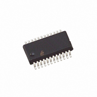
ISL6440IAZ-T Intersil, ISL6440IAZ-T Datasheet - Page 5

ISL6440IAZ-T
Manufacturer Part Number
ISL6440IAZ-T
Description
IC PWM BUCK CM 24QSOP
Manufacturer
Intersil
Datasheet
1.ISL6440IAZ-T.pdf
(15 pages)
Specifications of ISL6440IAZ-T
Pwm Type
Current Mode
Number Of Outputs
2
Frequency - Max
340kHz
Duty Cycle
93%
Voltage - Supply
4.5 V ~ 24 V
Buck
Yes
Boost
No
Flyback
No
Inverting
No
Doubler
No
Divider
No
Cuk
No
Isolated
No
Operating Temperature
-40°C ~ 85°C
Package / Case
24-QSOP
Frequency-max
340kHz
Rohs Compliant
YES
Lead Free Status / RoHS Status
Lead free / RoHS Compliant
Other names
ISL6440IAZ-TTR
Available stocks
Company
Part Number
Manufacturer
Quantity
Price
Part Number:
ISL6440IAZ-T
Manufacturer:
INTERSIL
Quantity:
20 000
Company:
Part Number:
ISL6440IAZ-TK
Manufacturer:
Intersil
Quantity:
1 550
Part Number:
ISL6440IAZ-TK
Manufacturer:
INTERSIL
Quantity:
20 000
Electrical Specifications
NOTES:
PWM CONTROLLER ERROR AMPLIFIERS
DC Gain (Note 7)
Gain-Bandwidth Product (Note 7)
Slew Rate (Note 7)
Maximum Output Voltage (Note 7)
Minimum Output Voltage (Note 7)
PWM CONTROLLER GATE DRIVERS (Note 8)
Sink/Source Current
Upper Drive Pull-Up Resistance
Upper Drive Pull-Down Resistance
Lower Drive Pull-Up Resistance
Lower Drive Pull-Down Resistance
Rise Time
Fall Time
POWER GOOD AND CONTROL FUNCTIONS
PGOOD LOW Level Voltage
PGOOD Leakage Current
PGOOD Upper Threshold, PWM 1 and 2
PGOOD Lower Threshold, PWM 1 and 2
ISEN and CURRENT LIMIT
Full Scale Input Current (Note 9)
Overcurrent Threshold (Note 9)
OCSET (Current Limit) Voltage
SOFT-START
Soft-Start Current
PROTECTION
Thermal Shutdown
2. Specifications at -40°C and 85°C are guaranteed by design, not production tested.
3. In normal operation, where the device is supplied with voltage on the V
4. This is the total shutdown current with VIN = VCC_5V = PVCC = 5V.
5. Operating current is the supply current consumed when the device is active but not switching. It does not include gate drive current.
6. The peak-to-peak sawtooth amplitude is production tested at 12V only; at 5V this parameter is guaranteed by design.
7. Guaranteed by design; not production tested.
8. Not production tested; guaranteed by characterization only.
9. Guaranteed by design. The full scale current of 32µA is recommended for optimum current sample and hold operation. See the Feedback Loop
When the VCC_5V pin is used as a 5V supply input, the internal LDO regulator is disabled and the V
VCC_5V pin. (Refer to the Pin Descriptions section for more details.)
Compensation Section below.
PARAMETER
5
Recommended operating conditions unless otherwise noted. Refer to Block Diagram and Typical Application
Schematic. V
Typical values are at T
IN
= 5.6V to 24V, or VCC5 = 5V ±10%, T
VCC5 = 4.5V
VCC5 = 4.5V
VCC5 = 4.5V
VCC5 = 4.5V
C
C
Pull-up = 100kΩ
Fraction of set point
Fraction of set point
ROCSET = 110kΩ
Rising
Hysteresis
OUT
OUT
A
= 25°C (Continued)
= 1000pF
= 1000pF
TEST CONDITIONS
ISL6440
IN
pin, the VCC_5V pin provides a 5V output capable of 60mA (min).
A
= -40°C to 85°C (Note 3),
MIN
105
5.9
0.9
80
80
-
-
-
-
-
-
-
-
-
-
-
-
-
-
-
-
-
IN
input pin must be connected to the
TYP
1.75
400
150
2.0
3.2
1.8
0.1
20
88
18
18
32
64
8
8
5
-
-
-
-
-
-
MAX
±1.0
120
3.6
0.5
95
-
-
-
-
-
-
-
-
-
-
-
-
-
-
-
-
-
October 4, 2005
UNITS
MHz
V/µs
mA
dB
µA
µA
µA
µA
ns
ns
°C
°C
%
%
FN9040.2
V
V
V
V


