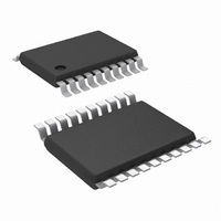
LM5035BMHX/NOPB National Semiconductor, LM5035BMHX/NOPB Datasheet - Page 22

LM5035BMHX/NOPB
Manufacturer Part Number
LM5035BMHX/NOPB
Description
IC CTRLR BRIDGE PWM 105V 20TSSOP
Manufacturer
National Semiconductor
Series
PowerWise®r
Datasheet
1.LM5035BMHNOPB.pdf
(28 pages)
Specifications of LM5035BMHX/NOPB
Pwm Type
Voltage Mode
Number Of Outputs
1
Frequency - Max
1MHz
Voltage - Supply
13 V ~ 105 V
Buck
No
Boost
No
Flyback
No
Inverting
No
Doubler
No
Divider
No
Cuk
No
Isolated
Yes
Operating Temperature
-40°C ~ 125°C
Package / Case
20-TSSOP Exposed Pad, 20-eTSSOP, 20-HTSSOP
Frequency-max
2MHz
Lead Free Status / RoHS Status
Lead free / RoHS Compliant
Duty Cycle
-
Other names
LM5035BMHX
Available stocks
Company
Part Number
Manufacturer
Quantity
Price
Company:
Part Number:
LM5035BMHX/NOPB
Manufacturer:
NS/TI
Quantity:
800
www.national.com
current in the zener diode amplified by the opto-coupler’s gain
could falsely trip the protection latch. R1 and Q1 are added
reduce the sensitivity to low level currents in the opto-coupler.
Using the values of
rent must equal V
Figure 15
Remote Thermal Protection using a thermistor (or multiple
thermistors) which may be located near the main heat
sources of the power supply. The negative temperature co-
efficient (NTC) thermistor is nearly logarithmic, and in this
example a 100kΩ thermistor with the β material constant of
4500 kelvins changes to approximately 2 kΩ at 130°C. Setting
R1 to one-third of this resistance (665Ω) establishes 130°C
as the desired trip point (for V
HICCUP MODE CURRENT LIMIT RESTART (RES)
The basic operation of the hiccup mode current limit restart is
described in the functional description. The delay time to
restart is programmed with the selection of the RES pin ca-
pacitor C
In the case of continuous cycle-by-cycle current limit detec-
tion at the CS pin, the time required for C
hiccup mode threshold is:
RES
shows an application of the OVP comparator for
as illustrated in
BE(Q1)
Figure
/ R1 = 350 µA before OVP latches.
14, the opto-coupler collector cur-
REF
Figure
= 5V). In a temperature band
15.
FIGURE 14. Latched Load Over-Voltage Protection
RES
FIGURE 15. Remote Thermal Protection
to reach the 2.5V
22
Once the controller has switched to standby mode, the out-
puts no longer switch but the VCC and REF regulators con-
tinue functioning and supply bias to the external circuitry. VCC
must fall below 6.2V or the UVLO pin must fall below 0.4V to
clear the OVP latch.
from 20°C below to 20°C above the OVP threshold, the volt-
age divider is nearly linear with 25 mV per°C sensitivity.
R2 provides temperature hysteresis by raising the OVP com-
parator input by R2 x 23 µA. For example, if a 22kΩ resistor
is selected for R2, then the OVP pin voltage will increase by
22 kΩ x 23 µA = 506 mV. The NTC temperature must there-
fore fall by 506mV / 25mV per°C = 20°C before the LM5035B
switches from the standby mode to the normal mode.
For example, if C
1.14 ms.
The cool down time, t2 is set by the soft-start capacitor (C
and the internal 1 µA SS current source, and is equal to:
If C
The soft-start time t3 is set by the internal 110 µA current
source, and is equal to:
SS
= 0.01 µF t2 is
RES
≊
= 0.01 µF the time t1 is approximately
10 ms.
30091338
30091337
SS
)


