ISL6745AUZ Intersil, ISL6745AUZ Datasheet
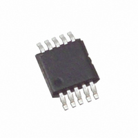
IC CTRLR PWM DBL ENDED 10-MSOP

ISL6745AUZ

Manufacturer Part Number
ISL6745AUZ
Description
IC CTRLR PWM DBL ENDED 10-MSOP
Manufacturer
Intersil
Datasheet

Specifications of ISL6745AUZ

Pwm Type
Voltage Mode
Number Of Outputs
2
Frequency - Max
2MHz
Duty Cycle
100%
Voltage - Supply
9 V ~ 16 V
Buck
No
Boost
No
Flyback
No
Inverting
No
Doubler
No
Divider
No
Cuk
No
Isolated
No
Operating Temperature
-40°C ~ 105°C
Package / Case
10-MSOP, Micro10™, 10-uMAX, 10-uSOP
Frequency-max
2MHz
Lead Free Status / RoHS Status
Lead free / RoHS Compliant

Available stocks

Company
Part Number
Manufacturer
Quantity
Price
Part Number:
ISL6745AUZ
Manufacturer:
Intersil
Quantity:
123
Part Number:
ISL6745AUZ-T
Manufacturer:
INTERSIL
Quantity:
20 000
Bridge Controller with Precision Dead
Time Control
The ISL6745 is a low-cost double-ended voltage-mode
PWM controller designed for half-bridge and full-bridge
power supplies and line-regulated bus converters. It
provides precise control of switching frequency, adjustable
soft-start, and overcurrent shutdown. In addition, the
ISL6745 allows for accurate adjustment of MOSFET non-
overlap time (“deadtime”) with deadtimes as low as 35ns,
allowing power engineers to optimize the efficiency of open-
loop bus converters. The ISL6745 also includes a control
voltage input for closed-loop PWM and line voltage feed-
forward functions.
Low start-up and operating currents allow for easy biasing in
both AC/DC and DC/DC applications. This advanced
BiCMOS design also features adjustable switching
frequency up to 1MHz, 1A FET drivers, and very low
propagation delays for a fast response to overcurrent faults.
The ISL6745 is available in a space-saving MSOP-10
package and is guaranteed to meet rated specifications over
a wide -40°C to 105°C temperature range.
Ordering Information
Add -T suffix to part number for tape and reel packaging
NOTE: Intersil Pb-free plus anneal products employ special Pb-free
material sets; molding compounds/die attach materials and 100%
matte tin plate termination finish, which are RoHS compliant and
compatible with both SnPb and Pb-free soldering operations. Intersil
Pb-free products are MSL classified at Pb-free peak reflow
temperatures that meet or exceed the Pb-free requirements of
IPC/JEDEC J STD-020.
ISL6745AU
ISL6745AUZ
(See Note)
PART NUMBER
TEMP. RANGE
-40 to 105
-40 to 105
(°C)
®
1
10 Ld MSOP
10 Ld MSOP
(Pb-free)
Data Sheet
PACKAGE
M10.118
M10.118
DWG. #
PKG.
1-888-INTERSIL or 1-888-468-3774
CAUTION: These devices are sensitive to electrostatic discharge; follow proper IC Handling Procedures.
Features
• Precision Duty Cycle and Deadtime Control
• 100
• Adjustable Delayed Overcurrent Shutdown and Re-Start
• Adjustable Oscillator Frequency Up to 2MHz
• 1A MOSFET Gate Drivers
• Adjustable Soft-Start
• Internal Over Temperature Protection
• 35ns Control to Output Propagation Delay
• Small Size and Minimal External Component Count
• Input Undervoltage Protection
• Pb-Free Plus Anneal Available (RoHS Compliant)
Applications
• Half-bridge Converters
• Full-bridge Converters
• Line-regulated Bus Converters
• AC/DC Power Supplies
• Telecom, Datacom, and File Server Power
Pinout
September 1, 2005
µ
A Start-up Current
All other trademarks mentioned are the property of their respective owners.
|
Intersil (and design) is a registered trademark of Intersil Americas Inc.
Copyright © Intersil Americas Inc. 2004-2005. All Rights Reserved
VERR
RTD
SS 1
CS
CT
2
4
5
3
ISL6745 (MSOP)
TOP VIEW
10
9
8
7
6
VDD
VDDP
OUTB
OUTA
GND
ISL6745
FN9161.6

Related parts for ISL6745AUZ

ISL6745AUZ Summary of contents

Page 1

... TEMP. RANGE PART NUMBER (°C) PACKAGE ISL6745AU -40 to 105 10 Ld MSOP ISL6745AUZ -40 to 105 10 Ld MSOP (See Note) (Pb-free) Add -T suffix to part number for tape and reel packaging NOTE: Intersil Pb-free plus anneal products employ special Pb-free material sets; molding compounds/die attach materials and 100% matte tin plate termination finish, which are RoHS compliant and compatible with both SnPb and Pb-free soldering operations ...

Page 2

Internal Architecture V DD UVLO + - INTERNAL BG OT SHUTDOWN 130 - 150 C GND R 2 RTD V BIAS 160 PEAK 2 VALLEY 0 ...

Page 3

Absolute Maximum Ratings Supply Voltage GND - 0.3V to +20.0V DD OUTA, OUTB . . . . . . . ...

Page 4

Electrical Specifications Recommended operating conditions unless otherwise noted. Refer to Block Diagram and Typical Application schematic. 9V < 25°C (Continued) A PARAMETER OSCILLATOR Charge Current R Voltage TD Discharge Current Gain C Valley Voltage T C Peak ...

Page 5

Typical Performance Curves 0.01 0.02 0.03 0.04 0.05 0.06 RTD CURRENT (mA) FIGURE 1. OSCILLATOR CT DISCHARGE CURRENT GAIN 600 500 400 300 200 100 0 100 200 300 400 500 600 CT (pF) ...

Page 6

Pin Descriptions the power connection for the IC. To optimize DD DD noise immunity, bypass V to GND with a ceramic DD capacitor as close to the V and GND pins as possible. DD The total ...

Page 7

R (Figure 5), and in charge current TD (Figure 4), results from Equation 2 would differ from the calculated frequency. The typical performance curves may be used as a tool along with the previous equations as ...

Page 8

... Accordingly, the reader is cautioned to verify that data sheets are current before placing orders. Information furnished by Intersil is believed to be accurate and reliable. However, no responsibility is assumed by Intersil or its subsidiaries for its use; nor for any infringements of patents or other rights of third parties which may result from its use ...

Related keywords