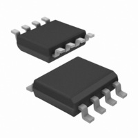
IR3637STRPBF International Rectifier, IR3637STRPBF Datasheet - Page 2

IR3637STRPBF
Manufacturer Part Number
IR3637STRPBF
Description
IC SYNC BUCK REGULATOR 8 SOIC
Manufacturer
International Rectifier
Datasheet
1.IR3637STRPBF.pdf
(21 pages)
Specifications of IR3637STRPBF
Pwm Type
Voltage Mode
Number Of Outputs
1
Frequency - Max
440kHz
Duty Cycle
85%
Voltage - Supply
4.5 V ~ 14 V
Buck
Yes
Boost
No
Flyback
No
Inverting
No
Doubler
No
Divider
No
Cuk
No
Isolated
No
Operating Temperature
0°C ~ 125°C
Package / Case
8-SOIC (3.9mm Width)
Frequency-max
440kHz
Output Current
15A
Frequency
400kHz
Supply Voltage Range
4.5V To 5.5V
Digital Ic Case Style
SOIC
No. Of Pins
8
Operating Temperature Range
0°C To +125°C
Termination Type
SMD
Rohs Compliant
Yes
Filter Terminals
SMD
Controller Type
PWM
For Use With
IRPP3637-12A - KIT REF DES 12A 1PH SYNC BUCKIRDC3637 - BOARD EVAL SYNC BUCK REGULATOR
Lead Free Status / RoHS Status
Lead free / RoHS Compliant
Other names
IR3637STRPBF
IR3637STRPBFTR
IR3637STRPBFTR
Available stocks
Company
Part Number
Manufacturer
Quantity
Price
Part Number:
IR3637STRPBF
Manufacturer:
IR
Quantity:
20 000
IR3637SPBF
ABSOLUTE MAXIMUM RATINGS
Vcc Supply Voltage ................................................
Vc Supply Voltage ..................................................
Storage Temperature Range .....................................
Operating Junction Temperature Range .....................
ESD Classification .................................................
Moisture Sensitivity Level ........................................
PACKAGE INFORMATION
ELECTRICAL SPECIFICATIONS
Unless otherwise specified, these specifications apply over Vcc=5V, Vc=12V and 0°C<Tj<125°C.
PARAMETER
Feedback Voltage
Fb Voltage
Fb Voltage Line Regulation
UVLO
UVLO Threshold - Vcc
UVLO Hysteresis - Vcc
UVLO Threshold - Vc
UVLO Hysteresis - Vc
UVLO Threshold - Fb
Supply Current
Vcc Dynamic Supply Current
Vc Dynamic Supply Current
Vcc Static Supply Current
Vc Static Supply Current
Soft-Start Section
Charge Current
Shutdown Threshold
Note1: Guaranteed by design. Not production tested.
2
Caution:
ratings only and function of the device at these or any other conditions beyond those indicated in the operational sections of the specifica-
tions is not implied. Exposure to “Absolute Maximum Rating” conditions for extended periods may affect device reliability
LDrv
Gnd
Vcc
Fb
θ
θ
1
2
3
4
JA
JC
=154°C/W
=41.2°C/W
Stresses above those listed in “Absolute Maximum Rating” may cause permanent damage to the device. These are stress
8
7
6
5
SS/SD
Comp
Vc
HDrv
UVLO Vcc
UVLO Vc
UVLO Fb
Dyn Icc
SYM
Dyn Ic
L
SS
V
I
SD
I
CCQ
REG
CQ
FB
IB
25°C<Tj<75°C
0°C<Tj<125°C
4.5<Vcc<5.5
Supply Ramping Up
Supply Ramping Up
Fb Ramping Down
Freq=400kHz, C
Freq=400kHz, C
SS=0V
SS=0V
SS=0V
Note1
TEST CONDITION
www.irf.com
Recommended Operating Conditions
Parameter
HMB Class 2 (2KV) JEDEC Standard
JEDEC Level 1 @ 260°C
Vcc
Vc
-65°C To 150°C
16V
0°C To 125°C
L
L
25V
=1500pF
=1500pF
Min
8
4.5
0.792
0.789
MIN
4.0
3.1
0.3
0.5
-15
4
6
1
0.800
0.800
TYP
0.25
4.2
3.3
0.2
0.4
3.3
-25
15
8
1
Max
5.5
14
0.808
0.811
MAX
0.1
4.4
3.5
0.5
4.7
-35
0.4
16
20
6
Units
V
V
UNITS
mA
mA
mA
mA
06/16/05
µA
%
Rev.1.1
V
V
V
V
V
V
V
V


