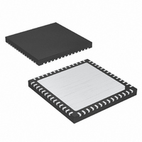
MAX5043ETN+ Maxim Integrated Products, MAX5043ETN+ Datasheet - Page 2

MAX5043ETN+
Manufacturer Part Number
MAX5043ETN+
Description
IC PWR W/MOSFET HS 56-TQFN
Manufacturer
Maxim Integrated Products
Datasheet
1.MAX5042ATN.pdf
(22 pages)
Specifications of MAX5043ETN+
Package / Case
56-TQFN
Voltage - Supply
20 V ~ 76 V
Frequency-max
500kHz
Operating Temperature
-40°C ~ 85°C
Number Of Outputs
1
Duty Cycle
47%
Pwm Type
Voltage/Current Mode
Buck
No
Boost
No
Flyback
Yes
Inverting
No
Doubler
No
Divider
No
Cuk
No
Isolated
Yes
Lead Free Status / RoHS Status
Lead free / RoHS Compliant
ABSOLUTE MAXIMUM RATINGS
PWMNEG, POSINPWM, DRNH,
BST to NEGIN.........................................................-0.3V to +95V
BST to XFRMRH .....................................................-0.3V to +12V
SRC to PWMNEG .....................................................-0.3V to +6V
REG15 to PWMNEG ...............................................-0.3V to +40V
REG15 to POSINPWM ............................................-80V to +0.3V
REG9, DRVIN to PWMNEG ....................................-0.3V to +12V
REG5 to PWMNEG ...................................................-0.3V to +6V
REG15
REG9 Current......................................................................40mA
REG5 Current......................................................................20mA
UVLO, RAMP, CSS, FLTINT, CSOUT,
OPTO, PWMSD, SYNC, CSP, CSN,
PPWM to PWMNEG .................................-0.3V to (REG5 + 0.3V)
PPWM Current .................................................................±20mA
PWMPNEG to PWMNEG .......................................-0.3V to +0.3V
DRNH Continuous Average Current (all pins combined)
Two-Switch Power ICs with Integrated
Power MOSFETs and Hot-Swap Controller
(See the Absolute Maximum Ratings Diagram below to better understand the absolute maximum ratings of the various blocks.)
Stresses beyond those listed under “Absolute Maximum Ratings” may cause permanent damage to the device. These are stress ratings only, and functional
operation of the device at these or any other conditions beyond those indicated in the operational sections of the specifications is not implied. Exposure to
absolute maximum rating conditions for extended periods may affect device reliability.
2
XFRMRH, XFRMRL, SRC to NEGIN....................-0.3V to +80V
RCFF, RCOSC to PWMNEG ...............................-0.3V to +12V
DRVDEL to PWMNEG...........................................-0.3V to +6V
T
T
J
J
_______________________________________________________________________________________
= +125°C.........................................................................2A
= +150°C......................................................................1.4A
Current..................................................................±80mA
80V
80V
80V
40V
80V
12V
12V
12V
4V
6V
4V
POSINHS,
POSINPWM
BST
XFRMRH, DRNH
XFRMRL
REG15
REG9, UVLO, RAMP, CSS, FLTINT,
CSOUT, RCFF, RCOSC, DRVIN
REG5, OPTO, PWMSD, SYNC, CSP,
CSN, DRVDEL, SRC, PPWM
PWMNEG,
PWMPNEG,
HSDRAIN,
HSOK
HSGATE
HSEN
IC SUBSTRATE, NEGIN
DEN
Absolute Maximum Ratings Diagram
XFRMRH Continuous Average Current (all pins combined)
XFRMRL Continuous Average Current (all pins combined)
SRC Continuous Current (all pins combined)
POSINHS to NEGIN................................................-0.3V to +80V
HSEN to NEGIN........................................................-0.3V to +4V
DEN to PWMNEG .....................................................-0.3V to +4V
HSGATE to NEGIN .................................................-0.3V to +12V
HSDRAIN, HSOK to NEGIN....................................-0.3V to +80V
HSOK Current .....................................................................20mA
Continuous Power Dissipation (T
Junction to Ambient Thermal Resistance, θ
Operating Temperature Range
Junction Temperature ......................................................+150°C
Storage Temperature Range .............................-65°C to +150°C
Lead Temperature (soldering, 10s) .................................+300°C
T
T
T
T
T
T
56-Pin Thin QFN (derate 47.6mW/°C above +70°C) .......3.8W
MAX5042ATN ................................................-40°C to +125°C
MAX5043ETN ..................................................-40°C to +85°C
J
J
J
J
J
J
= +125°C.........................................................................2A
= +150°C......................................................................1.4A
= +125°C.........................................................................2A
= +150°C......................................................................1.4A
= +125°C.........................................................................2A
= +150°C......................................................................1.4A
80V
80V
95V
A
= +70°C)
JA
...............+21°C/W


