LM5020MM-1/NOPB National Semiconductor, LM5020MM-1/NOPB Datasheet - Page 5
LM5020MM-1/NOPB
Manufacturer Part Number
LM5020MM-1/NOPB
Description
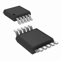
IC CONTROLLER PWM 100V 10-MSOP
Manufacturer
National Semiconductor
Series
PowerWise®r
Datasheet
1.LM5020MM-2NOPB.pdf
(13 pages)
Specifications of LM5020MM-1/NOPB
Pwm Type
Current Mode
Number Of Outputs
1
Frequency - Max
1MHz
Duty Cycle
85%
Voltage - Supply
13 V ~ 90 V
Buck
Yes
Boost
Yes
Flyback
Yes
Inverting
Yes
Doubler
No
Divider
No
Cuk
No
Isolated
No
Operating Temperature
-40°C ~ 125°C
Package / Case
10-MSOP, Micro10™, 10-uMAX, 10-uSOP
Frequency-max
1MHz
For Use With
LM5020EVAL - EVALUATION BOARD FOR LM5020
Lead Free Status / RoHS Status
Lead free / RoHS Compliant
Other names
LM5020MM-1
LM5020MM-1TR
LM5020MM-1TR
Available stocks
Company
Part Number
Manufacturer
Quantity
Price
Company:

Part Number:
LM5020MM-1/NOPB
Manufacturer:
TI
Quantity:
15 000
Company:
Part Number:
LM5020MM-1/NOPB
Manufacturer:
NSC
Quantity:
3 000
Part Number:
LM5020MM-1/NOPB
Manufacturer:
NS/国半
Quantity:
20 000


Oscillator
PWM Comparator
Slope Compensation
Output Section
Thermal Shutdown
Tsd
Electrical Characteristics
Specifications in standard type face are for T
perature range. Unless otherwise specified: VIN = 48V, VCC = 10V, and RT = 31.6kΩ. (Note 3)
Note 1: Absolute Maximum Ratings are limits beyond which damage to the device may occur. Operating Ratings are conditions under which operation of the device
is intended to be functional. For guaranteed specifications and test conditions, see the Electrical Characteristics.
Note 2: The human body model is a 100 pF capacitor discharged through a 1.5kΩ resistor.
Note 3: Limits are 100% production tested at 25˚C. Limits over the operating temperature range are guaranteed through correlation using Statistical Quality Control
(SQC) methods. The limits are used to calculate National’s Average Outgoing Quality Level (AOQL).
Note 4: Device thermal limitations may limit usable range.
Note 5: Specification applies to the oscillator frequency. The operational frequency of the LM5020-2 devices is divided by two.
Symbol
Frequency1 (RT = 31.6k)
Frequency2 (RT = 9.76k)
Sync threshold
Delay to Output
Min Duty Cycle
Max Duty Cycle (-1 Device)
Max Duty Cycle (-2 Device)
COMP to PWM Comparator
Gain
COMP Open Circuit Voltage
COMP Short Circuit Current
Slope Comp Amplitude
(LM5020-1 Device Only)
Output High Saturation
Output Low Saturation
Rise Time
Fall Time
Thermal Shutdown Temp.
Thermal Shutdown Hysteresis
Parameter
(Continued)
J
= +25˚C and those in boldface type apply over the full operating junction tem-
(Note 5)
(Note 5)
COMP set to 2V,
CS stepped 0 to 0.4V,
Time to onset of OUT
transition low
COMP=0V
COMP=0V
Delta increase at PWM
Comparator to CS
Iout = 50mA, V
I
Cload = 1nF
Cload = 1nF
OUT
= 100mA, V
Conditions
CC
5
OUT
- V
OUT
Min
175
560
2.4
4.3
0.6
75
80
0.33
0.25
0.25
Typ
200
630
105
165
3.2
5.2
1.1
25
80
50
18
15
25
Max
0.75
0.75
225
700
130
3.8
6.1
1.5
85
0
www.national.com
Units
kHz
kHz
mA
mV
ns
ns
ns
˚C
˚C
%
%
%
V
V
V
V
Related parts for LM5020MM-1/NOPB
Image
Part Number
Description
Manufacturer
Datasheet
Request
R

Part Number:
Description:
IC CONTROLLER PWM 100V 10-MSOP
Manufacturer:
National Semiconductor
Datasheet:

Part Number:
Description:
Pulse Width Modulation (PWM) Controller IC
Manufacturer:
National Semiconductor
Datasheet:
Part Number:
Description:
Pulse Width Modulation (PWM) Controller IC
Manufacturer:
National Semiconductor

Part Number:
Description:
National Semiconductor [8-Bit D/A Converter]
Manufacturer:
National Semiconductor
Datasheet:
Part Number:
Description:
National Semiconductor [Media Coprocessor]
Manufacturer:
National Semiconductor
Datasheet:
Part Number:
Description:
Digitally Controlled Tone and Volume Circuit with Stereo Audio Power Amplifier, Microphone Preamp Stage and National 3D Sound
Manufacturer:
National Semiconductor
Datasheet:
Part Number:
Description:
Digitally Controlled Tone and Volume Circuit with Stereo Audio Power Amplifier, Microphone Preamp Stage and National 3D Sound
Manufacturer:
National Semiconductor
Datasheet:
Part Number:
Description:
AC97 Rev 2 Codec with Sample Rate Conversion and National 3D Sound
Manufacturer:
National Semiconductor
Part Number:
Description:
Manufacturer:
National Semiconductor
Datasheet:
Part Number:
Description:
Manufacturer:
National Semiconductor
Datasheet:
Part Number:
Description:
General Purpose, Low Voltage, Low Power, Rail-to-Rail Output Operational Amplifiers
Manufacturer:
National Semiconductor
Datasheet:
Part Number:
Description:
8-bit 20 MSPS flash A/D converter.
Manufacturer:
National Semiconductor
Datasheet:
Part Number:
Description:
Low Noise Quad Operational Amplifier
Manufacturer:
National Semiconductor
Datasheet:
Part Number:
Description:
Quad Differential Line Receivers
Manufacturer:
National Semiconductor
Datasheet: