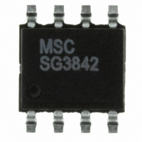
SG3842DM Microsemi Analog Mixed Signal Group, SG3842DM Datasheet - Page 14

SG3842DM
Manufacturer Part Number
SG3842DM
Description
IC PWM CURRENT MODE 8SOIC
Manufacturer
Microsemi Analog Mixed Signal Group
Datasheet
1.SG3842M.pdf
(14 pages)
Specifications of SG3842DM
Pwm Type
Current Mode
Number Of Outputs
1
Frequency - Max
500kHz
Duty Cycle
100%
Voltage - Supply
8.2 V ~ 30 V
Buck
No
Boost
No
Flyback
Yes
Inverting
No
Doubler
No
Divider
No
Cuk
No
Isolated
Yes
Operating Temperature
0°C ~ 70°C
Package / Case
8-SOIC
Frequency-max
500kHz
Lead Free Status / RoHS Status
Lead free / RoHS Compliant
SG1842/SG1843 Series
14
INPUT
AC
SPECIFICATIONS
Input line voltage:
Input frequency:
Switching frequency:
Output power:
Output voltage:
Output current:
Line regulation:
Load regulation:
Efficiency @ 25 Watts,
Output short-circuit current:
3.6kW
V
V
0.01µF
IN
IN
= 90VAC:
= 130VAC:
20kW
673-3
150kW
100pF
10kW
.0047µF
4.7W 1W
T Y P I C A L A P P L I C A T I O N C I R C U I T S
P R O D U C T D A T A B O O K 1 9 9 6 / 1 9 9 7
SG1842
V
COMP
V
R
T
FB
REF
/C
220µF
250V
16V
90VAC to 130VAC
50 or 60Hz
40KHz ±10%
25W maximum
5V +5%
2 to 5A
0.01%/V
8%/A*
70%
65%
2.5Amp average
C
T
U R R E N T
P
GND
V
R O D U C T I O N
CC
OUT
CUR
SEN
FIGURE 25. — OFF-LINE FLYBACK REGULATOR
56kW
1W
- M
0.01µF
27W
O D E
20kW
470pF
P W M C
1kW
* This circuit uses a low-cost feedback scheme in which the DC
1N3613
D
voltage developed from the primary-side control winding is
sensed by the SG1842 error amplifier. Load regulation is
therefore dependent on the coupling between secondary
and control windings, and on transformer leakage
inductance.
10µF
20V
A T A
O N T R O L L E R
0.85W
0.01pF
400V
1N3613
S
H E E T
820pF
(continued)
2.5kW
BOUNDARY
ISOLATION
TI
T1: Coilcraft E - 4140 - b
Primary - 97 turns
Secondary - 4 turns
Control - 9 turns
single AWG 24
4 parallel AWG 22
3 parallel AWG 28
USD 735
4700µF
10V
Copyright © 2000
Rev. 1.6a 10/04
2-5A
5V


